
All content Copyright 2022 Parallel Systems Ltd.
1. Select the buffer2.dsn file entry in the project Manager pane again and take Tools>Generate Part from the main menu.
2. Use the Browse button for Netlist / Source file to navigate to the buffer_sub.lib file.
(Previously saved to the C:\OrCAD_Training\PSpice folder.)
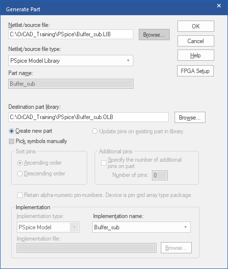
3. Leave the other defaults and left-click>OK
(The buffer_sub.olb gets added to the Project Manager pane)
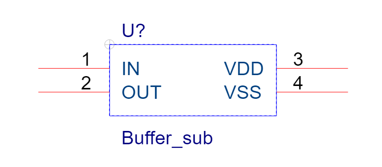
4. Double-click on the .\buffer2_sub.olb entry to expand the library and double-click on the buffer_sub entry to open the Part Editor. See that the “default” rectangle gets generated for the subcircuit.
5. Close the Part Editor. (Use the “X” on the tab, for example)
6. Close the buffer2 project. (Select the DSN file entry for “buffer2.dsn” and take File>Close)
7. Create a new project called Buffer3 based upon the Buffer project from previous labs.
8. Delete the LF411 and associated parts, you should be left with the DC and AC sources and the RC load circuit for the output.
9. Select Place>Part from the top menu.
10. Left-click the Add Library button and add Buffer_sub.olb.
Be sure to use the one from the C:\OrCAD_Training\PSpice directory. There is a buffer.olb file in the regular PSpice library folder, but that is not the one you want to use for this lab.
11. Find Buffer_sub in the list of parts and double-click on it.
12. Place a copy of the part in the schematic.
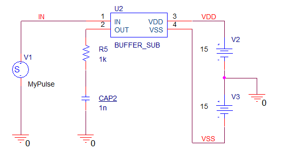
13. Using the circuit above for reference, connect the buffer part to the sources and load.
14. Check the simulation profile is still a transient analysis that runs for 5uS.
(This would be inherited from the original Buffer project)
15. In the simulation profile, left-click Configuration Files on the left hand side, select Library in the Category section, use the upper Browse button and locate the Buffer_sub.lib, in the C:\OrCAD_Training\PSpice directory, use Add to Design to add the model library.
16. Left-click>OK to close the simulation profile.
17. Run the simulation and examine the result in the Probe window. It should look like the results seen in Transient chapter, which are reproduced in the following graphic. (Add the Trace for I(CAP2) as before)
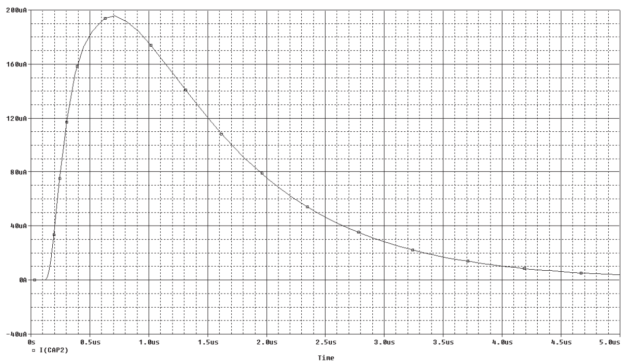
If the “based on” Buffer project retained the parametric sweep settings, you may have a message about “missing parameter CVAL” and you may need to edit the Simulation Profile to remove the Parametric Sweep option and repeat the simulation, or you may have 25 waveforms when the simulation completes if everything was correctly configured for the Parametric Sweep.

End of Lab
All content Copyright 2022 Parallel Systems Ltd.