
All content Copyright 2022 Parallel Systems Ltd.
1. If you have closed Lesson10, re-open it.
2. Using a text editor such as Notepad, view the contents of the Parts.upd file located in the C:\OrCAD_Training\Capture directory.
Note
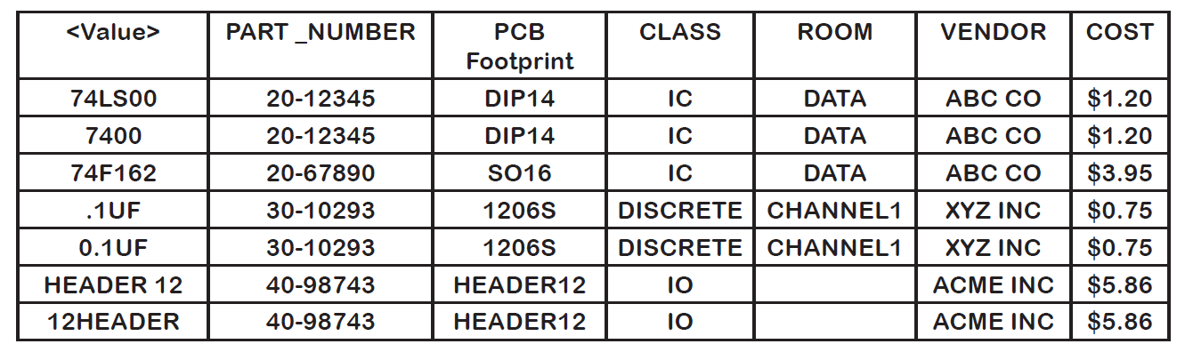
Although the Parts.upd file does not present the file content in table format, due to tab character handling, the following table aligns data into columns to more clearly present the content of the Parts.upd file. Notice how each part has six property values.
3. Close the Update Property file.
4. Right-click in the bar at the top of the session log and Clear Session Log as shown in the following graphic:
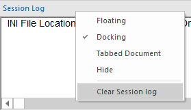
This clears the Session Log window of previous process results so that the only data present is the result of the part update process.
5. In the Project Manager, left-click on the design (dsn) file entry.
6. Select Tools>Update Properties from the top menu.
The Update Properties window appears.
7. In the Action section, make sure the Update parts option is selected.
8. Choose the Use case insensitive compares option.
9. To specify the Property Update File, left-click>Browse and navigate to the C:\OrCAD_Training\Capture directory.
10. Left-click on the Parts.upd file to select it and left-click>Open.
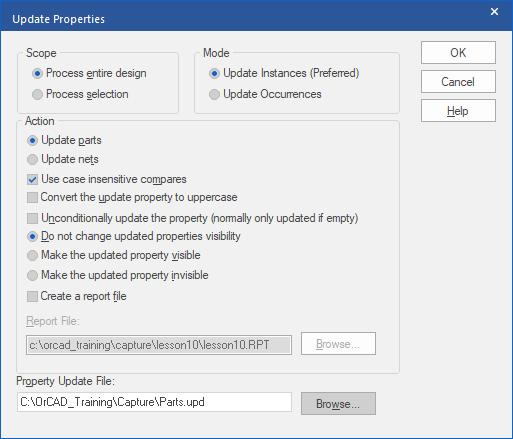
11. In the Update Properties window, left-click>OK.
The Capture tool loads the part properties into the design.
12. Select File>Save.
View the contents of the Session Log window. Observe that the update file is trying to add the same six properties to each of the parts in the design (PCB Footprint, PART_NUMBER, CLASS, ROOM, VENDOR, and COST). Also observe that when a part already has one of these properties assigned to it (from a previous lab), the part is not updated. (Unconditionally update would be required for this to happen)
13. Open PAGE1 of the design and double-click on one of the capacitors.
14. In the Property Editor window, set the Filter by field to <Current properties>.
Locate the PCB Footprint, PART_NUMBER, CLASS, ROOM, VENDOR, and COST properties. Compare the values in the spreadsheet to the picture of the part property file shown at the beginning of this lab.
15. Close the Property Editor.
16. Close PAGE1 of the schematic.
17. Using a text editor such as Notepad, view the contents of the Nets.upd file located in the C:\OrCAD_Training\Capture directory.
Note
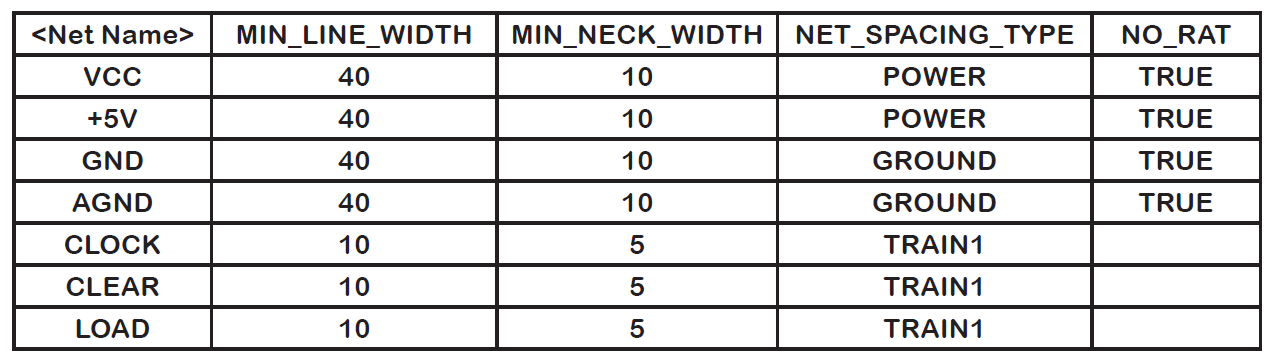
Although the Nets.upd file does not present file content in table format, the following table aligns data into columns to more clearly present content. Observe that four properties are assigned to each net in the file.
18. Close the update file.
19. In the Project Manager window, left-click on the design (dsn) file entry.
20. Select Tools>Update Properties.
The Update Properties window appears.
21. In the Action section, left-click the Update nets option.
22. Left-click>Browse, navigate to the Nets.upd file in the
C:\OrCAD_Training\Capture directory, and left-click>Open.
23. Left-click>OK to load the net properties into the design.
(Note that there are some errors listed in the Session Log because the Update attempts to attach properties to the invisible Power Pins, for example. Properties will be successfully added to any visible wires.)
24. Select File>Save from the top menu.
25. Open a schematic page.
26. Double-click the wire for net CLOCK.
27. In the Property Editor, left-click the Filter by option, select <Current Properties>
28. Locate the MIN_LINE_WIDTH and NET_SPACING_TYPE, and NO_RAT properties.
Note
The NO_RAT property turns off the display of a “rat-nest” line for a net in OrCAD PCB Editor. Global Power and GND nets receive this property (by default) through the PCB Editor netlist processing.
These properties were added by the supplied Nets.upd file.
29. Close the Property Editor.
30. Close the schematic page.
End of Lab
All content Copyright 2022 Parallel Systems Ltd.