
All content Copyright 2022 Parallel Systems Ltd.
1. In the Project Manager window of the intro.dsn, double-click PAGE1.
2. Enlarge the schematic window and zoom in to capacitors C1 and C2 and observe the colours of objects.
3. Select Options>Preferences.
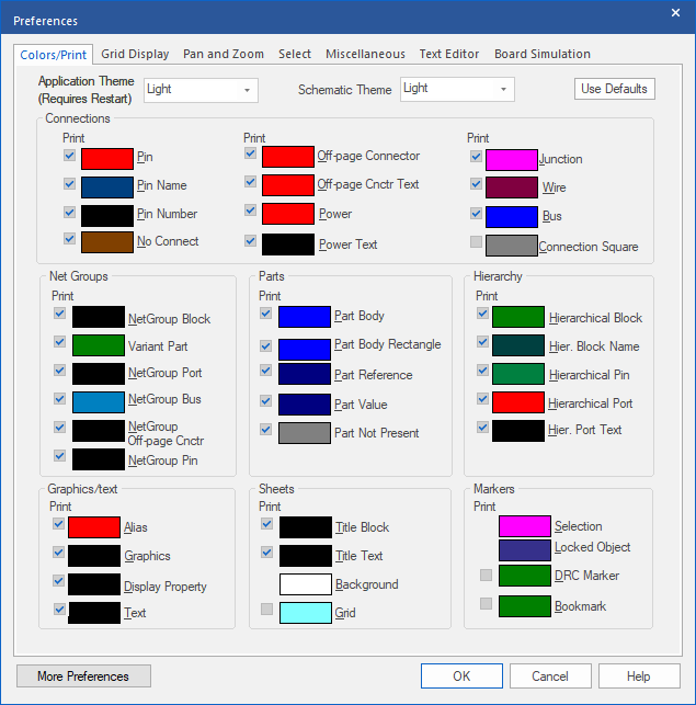
The Colors/Print tab is the first to be displayed. (Light Theme displayed)
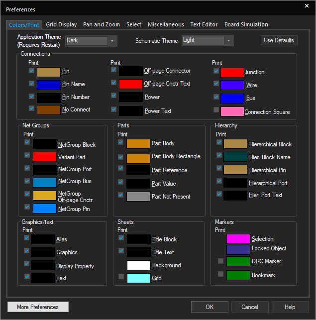
(Dark Theme displayed)
Note that Light and Dark Themes are available for the Schematic as well as for the frame and toolbars.
4. Left-click the colour box next to Part Body, left-click a different colour from the colour palette, then left-click>OK.
5. If necessary, change the colour assignments for Part Reference, Part Value, and Wire also.
6. Change the Grid colour to black so you can see it easily on the screen.
7. Left-click OK.
The colour assignments take effect immediately. These preferences are machine specific (any design opened on your system will use these colour settings).
Note
If your grid is not visible, use the View>Grid command to turn it on.
8. Select Options>Preferences.
9. Left-click the Use Defaults button in the lower right corner of the Colors/ Print tab, and left-click>OK.
The schematic displays the original colour assignments.
10. Try several more colour assignments (for example, Alias, Background, Junction, No Connect, Pin, Power, Power Text, and Title Block). Assigning colours to some of these objects helps you prepare for the design entry tasks covered in the next lesson.
11. Select Options>Preferences again.
12. Left-click the Select tab.
13. Change the Area Select setting for the Schematic Page Editor to Fully Enclosed and left-click>OK.
14. Go back to the Project Manager window, “intro” tab, and double-click on Page2 to open the schematic page.
15. Zoom in to U2A (74LS00).
16. Drag a selection rectangle across (but do not fully enclose) U2A.
Observe that the part is not selected.
17. Drag a larger selection rectangle and fully enclose U2A (including pin stubs).
Observe that the part is now selected.
18. Left-click in a blank area to deselect all objects.
19. Select Options>Preferences and left-click the Select tab.
20. Change the Area Select setting back to Intersecting and left-click>OK.
21. Drag a rectangle across a portion of U2A to select it.
Note
Two Icons on the Capture main tool bar also perform the same task without having to go to the User Preferences.
Intersecting  Fully Enclosed
22. Select Options>Preferences.
23. Left-click the Miscellaneous tab.
24. In the Auto Reference section, be sure the Automatically reference placed parts option is off / unchecked. Set the options as displayed in the following window.
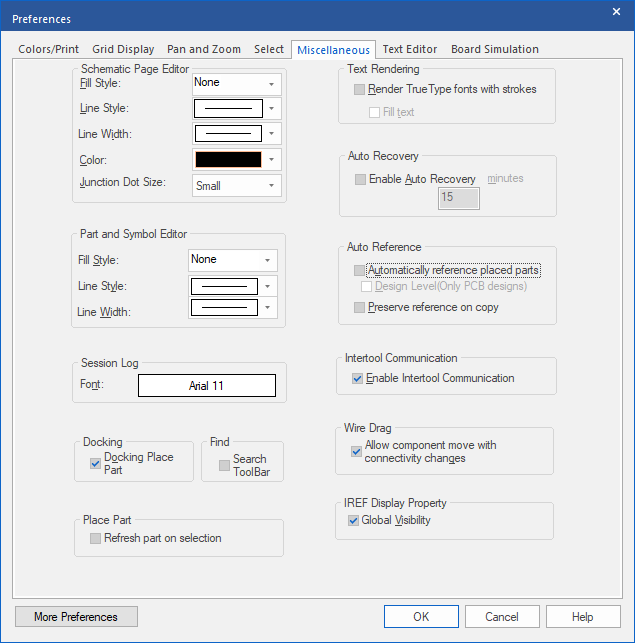
25. Left-click>OK.
26. Select File>Close.
The schematic window closes.
27. Select File>Close Project.
The Project Manager window closes. The main session window is still running.
End of Lab
All content Copyright 2022 Parallel Systems Ltd.