
All content Copyright 2022 Parallel Systems Ltd.
The following lab is only for testing the Heterogeneous Parts using the Annotate command.
1. Select File>New Design. (As this is only to illustrate how to Annotate your Heterogeneous parts, we will not use the formal settings for an .OPJ file.)
2. If necessary, browse to the C:\OrCAD_Training\Capture directory, and left-click>Select Folder.
3. When the page is open add the following gates to the page.
4. Select Place>Part.
5. When the Place Part tab opens, add the TRNG.OLB to the search path.
6. Now select the LM324 part from the TRNG.OLB library, as shown below:
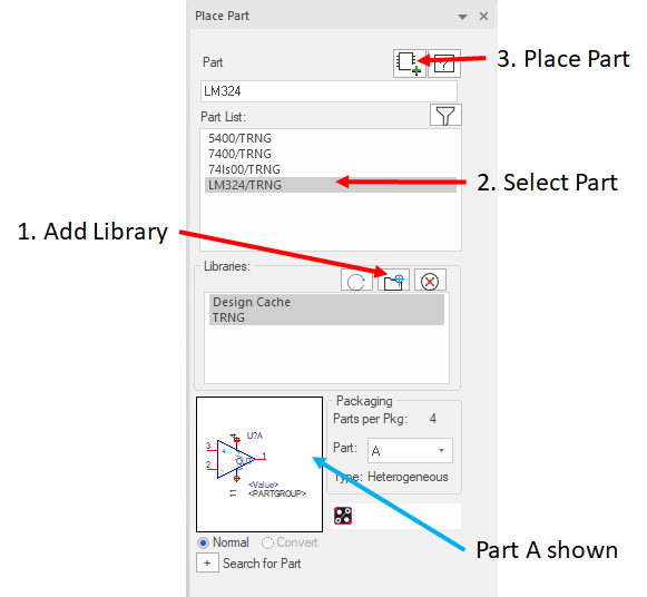
Notice that the Packaging section of the Place Part form shows four parts per package.
The Part field defaults to A, or section one of the package.
7. Place the part on the schematic page.
8. Add three more sections of the LM324 package into the schematic by toggling the Part field in the Place Part form to B, C, & D.
9. Repeat this until there are about 12 or 16 different “gates” on the page. COPY / PASTE can be used to achieve this.
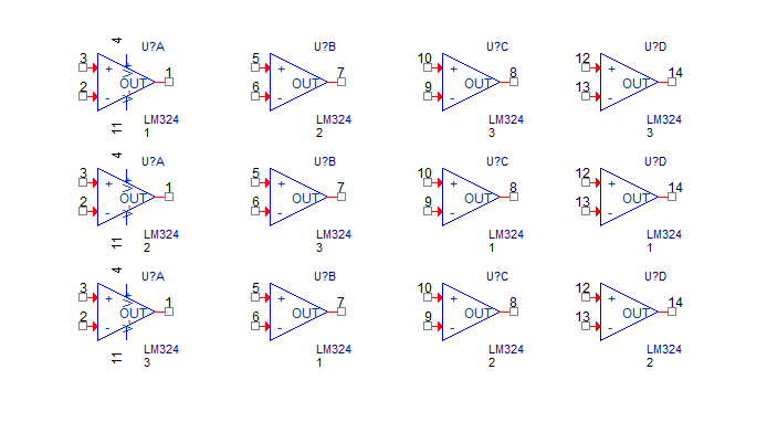
10. The page may look something like the following picture. It is not important how many of each gate type is placed. (Note: the PARTGROUP property has already been assigned and displayed in this picture)
11. Select four gates in the schematic page, one of each “A” “B” “C” and “D” gate.
12. Right-click>Edit Properties from the pop-up menu.
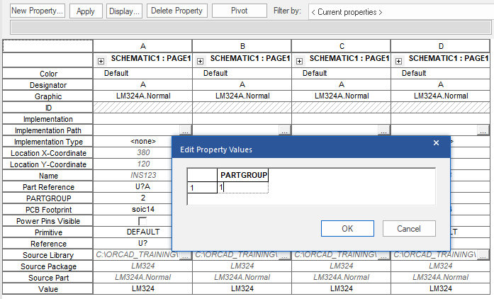
13. In the Property Editor window, left-click the Pivot button to get the Property Names listed on the left
14. Select the PARTGROUP property cell, to select the Property Name and four values, and, from the right-click popup menu, select Edit, set the PARTGROUP property value to 1 for the property.
Refer to the following illustration to see how this can be done.
15. Left-click>Apply and close the Property Editor.
16. Repeat this process until PARTGROUP has been assigned to all the gates.
17. Now, in the Project Manager window, highlight the design name entry, likely called design1.dsn.
18. Select Tools>Annotate.
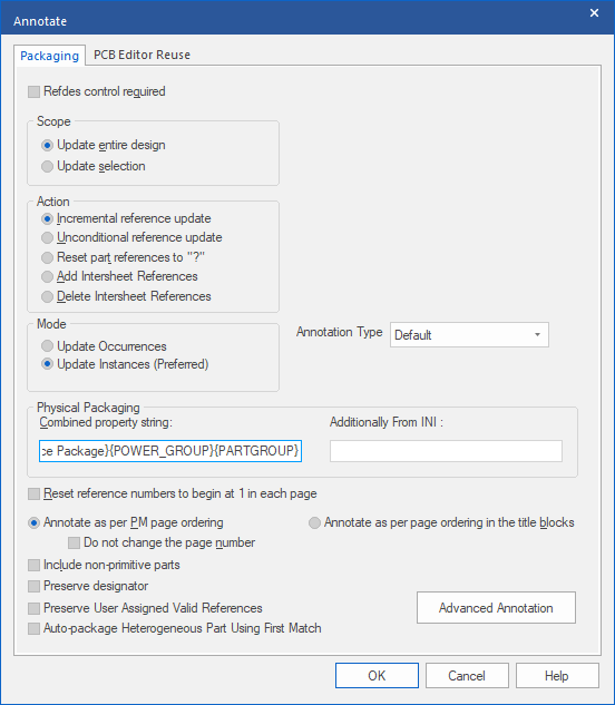
19. Under Physical Packaging, add the PARTGROUP property to the end of the Combined Property String.
20. Be sure to enclose the property name in curly braces, as shown in the following graphic.
(Note: If the {PARTGROUP} value is placed in the “Additionally from INI” box, the setting will be saved to the current Capture.ini file and will be applied to “all” projects)
21. Left-click>OK.
22. Check the schematic to see if the sections of the LM324 parts were placed into the same package (same reference designator).
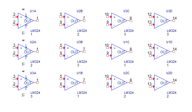
23. Close the test schematic but do not save it.
Note
If the PARTGROUP property had not been added to the Combined Property String, it would have been ignored during annotation, resulting in annotation failure.
Note
To pin swap in PCB Editor, the SPLIT_INST property must be added with a value of TRUE to all sections of a heterogeneous part, or use the SWAP_INFO property to control which sections of the part pins can be swapped between, again, this needs to be assigned to all sections of the heterogeneous part. There must not be any duplicate pins across the sections of the split part. See the section in the Capture User Guide on “Pin Swapping in the Capture-PCB Editor Flow”, or search the Capture Help for Pin Swapping. Many users consider that, for modern designs, swapping pins in the PCB is no longer desirable.
The “gates” of Heterogeneous parts may be swapped in PCB Editor where the Pin Names, Pin Types and Pin Group properties are identical. In this case the B, C, and D “gates” may be swapped with each other but NOT with the A “gate”.
24. When you have completed testing the part, exit the “design” but do not save it.

End of Lab
All content Copyright 2022 Parallel Systems Ltd.