
All content Copyright 2022 Parallel Systems Ltd.
1. In the Project Manager window, left-click the .\lesson8.dsn entry.
2. Select PCB>Design Rules Check, or left-click the Design Rules Check icon  in the main toolbar.
3. In the Options section, make sure the following selections are checked:
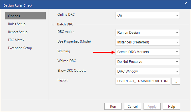
4. In the Rules Setup section, make sure that the following selections are checked:
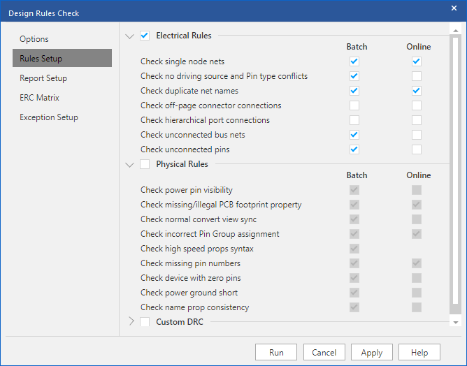
(No Physical Rules checking)
5. In the Report Setup section, make sure that the following selections are checked:
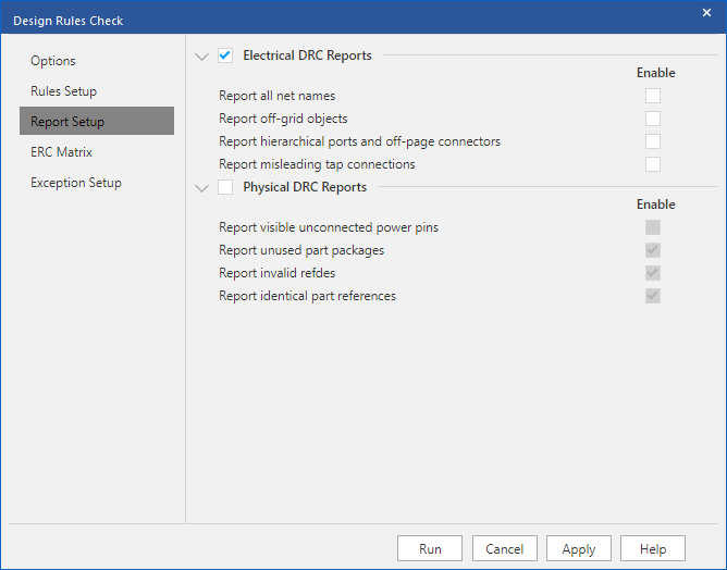
(No Physical Rules reports)
6. In the ERC Matrix section, make sure that the following selections are checked:
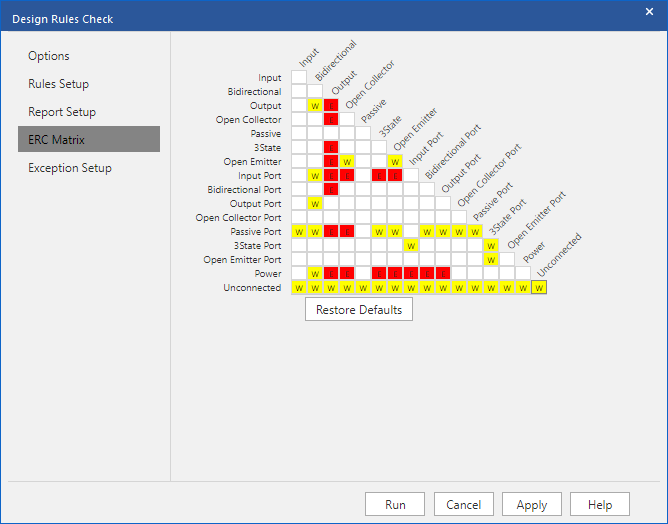
(This will flag any unconnected pins or ports as warnings)
7. Left-click>Run to check the schematic.
(“OK / Yes” any warning messages, “No” to view the Session Log)
8. Go to the Capture Project Manager window and double-click on the .\Lesson8.drc entry in “Outputs” to open the DRC report. The report contains warnings for an unconnected pin, nets with no driving source, and nets with fewer than two pins (one-pin signals).
9. Close the DRC results window.
These errors are also flagged with DRC markers on the schematic page. (Because the “Create DRC Markers for Warnings” was checked.
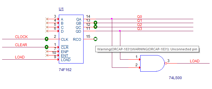
10. To get information about an error, hover the mouse over, or double-click on, the DRC marker.
Hover:
Double-click:
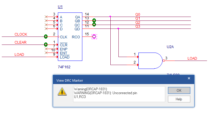
11. In the Project Manager window, highlight the design name entry, .\Lesson8.dsn.
12. Select Edit>Browse>DRC Markers from the top menu.
A “Browse” window will open with a list of all the DRC markers, their locations, and the type of error.
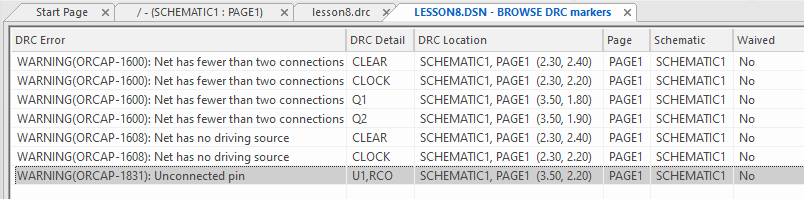
13. Double-click on the error message in the left hand column for “Unconnected Pin”.
The page with the error marker will open and the error marker will be highlighted.
14. Left-click the Place no connect icon, and add a “no connect” symbol on pin 15 of the 74F162.
15. Save the design.
16. Check the design again, PCB>Design Rules Check, Run
(The .\Lesson8.dsn entry must be selected in the Project Manager window).
17. Review the new DRC report and observe that the unconnected pin warning is gone.
(Use the No Connect symbol to notify the DRC processing that pins are intentionally left unconnected.)
18. Close the report.
19. In the schematic, observe that the error marker on pin 15 of U1 has been cleared.
Please do not fix the remaining errors. These problems are addressed in the next lesson.
End of Lab
All content Copyright 2022 Parallel Systems Ltd.