
All content Copyright 2022 Parallel Systems Ltd.
1. If required, open b4route.brd to continue with the design from the previous lab..
2. Select Setup>Cross Section and adjust the current stackup to match the screenshot below. For the purposes of this lab we will change two of the planes to conductors and rename the layers accordingly.
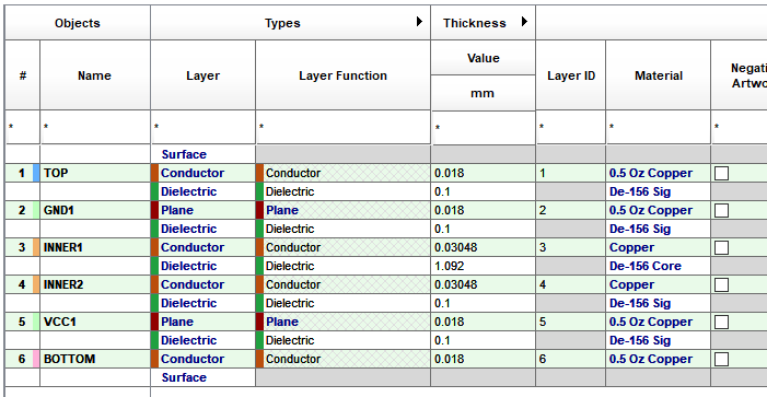
3. Left-click>OK the cross section editor and go to Setup>Colors and define colours for Inner1 and Inner2 layers. Rename the GND2 layer to VCC1.
4. Using the steps you learned from Session 10: Shapes, delete the copper shapes on Inner1 and Inner2 and change the Net Name of the shape now on layer VCC1 to VCC.
We now want to define some Blind and Buried Vias. This step may not be necessary for your own designs and the working layer method, but the purpose of this step is to show you the method to define these types of vias and then route using the Working Layer method.
5. Setup>Auto Define B/B Vias (rather than manually generate all of the Blind / Buried Vias required) and fill the form in as shown below. Left-click>Generate to create the blind and buried vias for all layers.
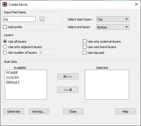
(Whilst generating the BB Vias, those Vias could be assigned to the Rule Sets, at the bottom of the form but, typically, having “any” layer to “any layer” BB Vias wouldn’t be cost effective to manufacture. The following steps show how to manually assign the Vias to the rules sets but, even so, the BB Vias are not filtered for any manufacturing optimisation)
6. Once complete you can use Viewlog to review the vias you have added. left click on Close to close the form and the red cross to close the log file.
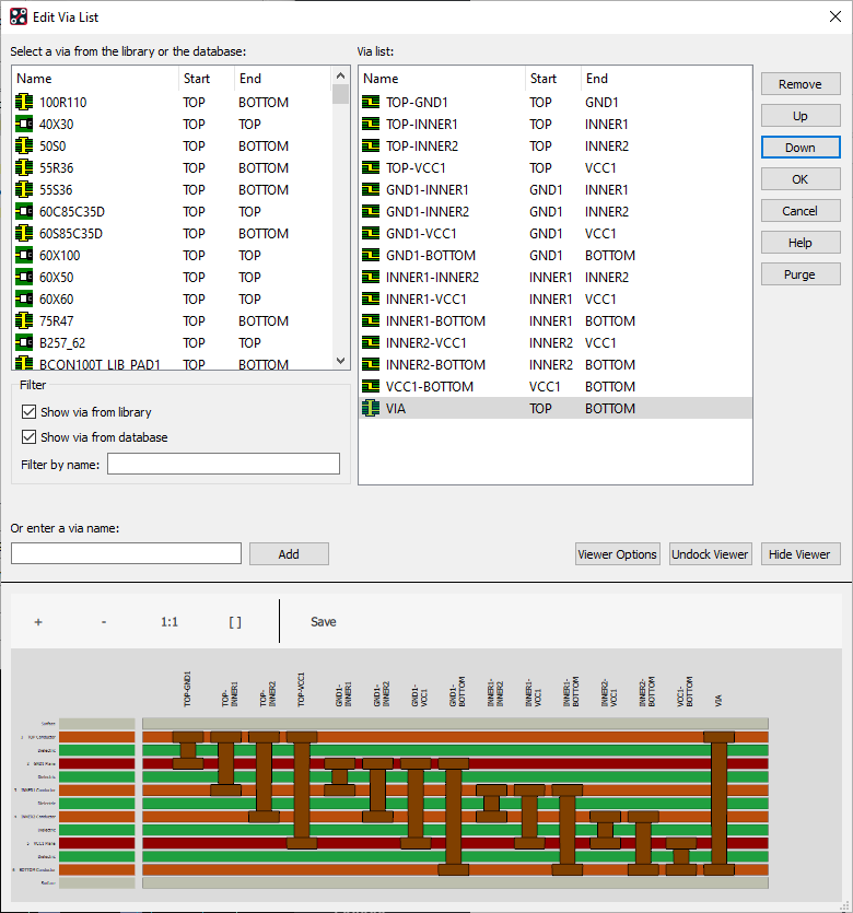
7. Launch Constraint Manager and go to Physical>Physical Constraint Set and notice that the DEFAULT rule has the additional vias added. Left click the Vias cell for DEFAULT to visualise the via order. The vias are graphically displayed on the viewer showing the layers that they span. The order of the via list is important. If a VIA which is a through hole via is at the top of the list then PCB Editor will always use this via by default because it can resolve any routing requirement from and to any layer, so it is recommended for designs that require blind and buried vias that the via list follow the order of the PCB stackup.
Since the TOP-BOTTOM via is a duplicate of VIA we can remove this from the list. Select TOP-BOTTOM and left-click>Remove.
We also need to move the VIA from the top of the list to the bottom, left-click on the VIA entry and use the Down button to move it to the bottom. Once complete your via list should match the screenshot below.
Left-click>OK and the vias are now available for use.
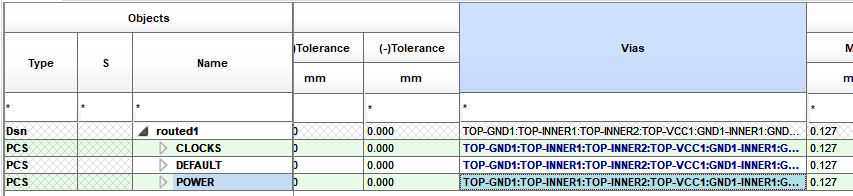
8. Right click the Vias cell for the DEFAULT rule and choose Copy, then right-click in the Via cells for the CLOCKS and POWER rules and choose Paste (Sso that the vias are available for all rules). Once complete close Constraint Manager.
9. Add a Connection, Route>Connect menu, or icon, and pick a connection to route, or left-click a connection in Etch Edit Mode.
10. Once in Add Connect, activate Options, note the Act(ive), current, routing layer and change the drop-down from Alt(ernate) to WL (Working Layer)
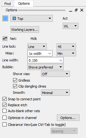
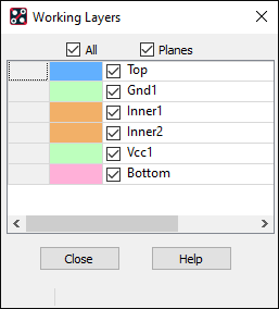
11. The Working Layers selection form appears to allow selection of which routing layers are to be used for this routing method, for this exercise, select Planes and All. This means that “any” layer can be selected for the “next” routing layer.
12. Move the mouse to the canvas and start adding some routing, then add a via, double-click, or right-click>Add Via.
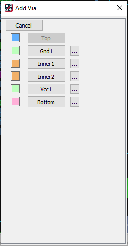
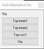
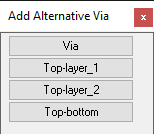
13. Add Via will then prompt for the layer to continue routing on. If the Layer name is chosen, the first available via from the via list that will make that connection is used, in this case Top-Inner1 but there is also a browse (…) button to allow the user to select the via to be used to connect between the Active layer and the next routing layer.
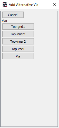

14. Continue routing for this and other nets experimenting with the Working Layer options.
15. If required. you can now complete this design and all the connections using the Working Layer method. Save this board as routed12-3.brd
Completing the routing of this board is not a requirement since the autorouter can be run on this board in the next Lab.
You can also just use the default VIA and the working layer method so that the completed design is a through hole design and not a blind and buried one.
If you want to do this then go back to the Physical Constraint Set Via lists and move the VIA to the top of the via list.
You can also remove the blind and buried vias to simplify the routing.
If you do complete the routing then this can be used going forward into the next lab but remember to save the design first.
End of Lab
All content Copyright 2022 Parallel Systems Ltd.