
All content Copyright 2022 Parallel Systems Ltd.
1. Open the routed.brd file if it is not already opened.
2. Zoom in to a close-up view of a portion of the board.
3. Left-click the Slide icon. 
4. Activate Find, select Vias and Cline Segs.
5. Set the Visibility for “all” Etch / Top tab as follows:
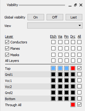
6. Left-click any segment of etch in your display. The segment you picked will travel with the cursor.
7. Choose a location for the moveable etch and left-click to define the new location.
Options controls corners that result after using Slide.
8. Experiment by changing the Options for Min Corner Size, Vertex Action, Bubble, Auto Join, and so on and sliding other etch segments. The default setting is for line corners.
9. Also try combinations with the Gridless and Allow DRCs options checked and unchecked to get a feel for how these choices restrict or open up sliding.
10. Now use the Slide command to slide a group of traces that are defined by dragging a window around them (left-click and drag).
11. The PCB Editor command window will prompt with “Waiting for origin pick”. Select the starting point and move to select the finishing point.
12. Right-click>Done from the pop-up menu.
13. Now move to an area where there are lots of traces that are routed together, either horizontally or vertically.
14. Select Setup>Application Mode>Etch Edit from the top menu, if you are not already in the Etch Edit mode.
15. Select and drag on a piece of etch to slide. When you have moved the etch to where you wish, release the LMB to place the etch at the new location.
16. Select Edit>More>Vertex from the top menu.
17. Left-click a corner or vertex on an etch line.
The corner of the etch line is now attached to the cursor, and can be moved to a new location.
18. Choose a new location and left-click at that point.
Now we will add a vertex to an etch segment.
19. Select a point anywhere between the ends of an etch segment.
This causes a new vertex point to be added.
20. Left-click a new location for the vertex.
21. Right-click>Done from the pop-up menu.
22. Select Edit>More>Vertex from the top menu.
23. Left-click on a corner or existing vertex point of an etch line.
24. Right-click>Delete Vertex.
The vertex is deleted, and the new trace path is shown.
25. Right-click>Done from the pop-up menu.
26. Practise using the Pre-select mode to add, move and delete vertices.
Move the mouse anywhere between the ends of an etch segment and right-click>Add Vertex to create and move a new vertex. Move the mouse over a vertex, and the cursor will change shape to a small orthogonal cross, then a right-click can be used to select either Move Vertex or Delete Vertex.
End of Lab
All content Copyright 2022 Parallel Systems Ltd.