
All content Copyright 2022 Parallel Systems Ltd.
1. If it is not already open, open the constraints.brd
2. Start the Constraint Manager, Setup>Constraints, for example.
3. In the Constraint Manager, left-click on Manufacturing at the left and left-click the “>” icons to open the Manufacturing options as shown below.
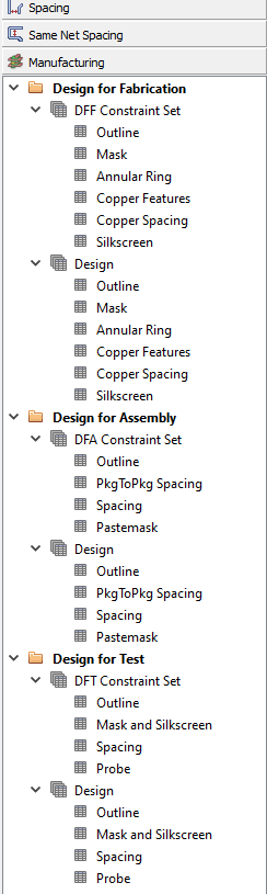
4. Left-click on Annular Ring in DFF Constraint Set
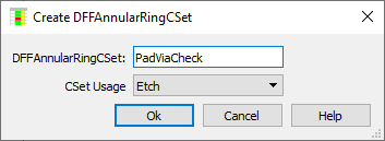
5. Left-click in the “<Create New>” cell
6. Set the name of the new check to PadViaCheck and left-click>OK
7. Left-click in the Hole to Pad and set the value to 0.125mm for both All Pins and All Vias

(If you don’t get the same view, use the View>Transpose from the menu to change it)
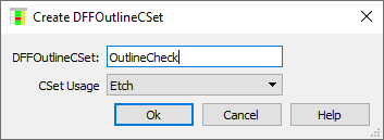
8. Left-click on Outline in DFF Constraint Set
9. Left-click the “New CSET” cell and set the name of the new check to OutlineCheck and left-click>OK
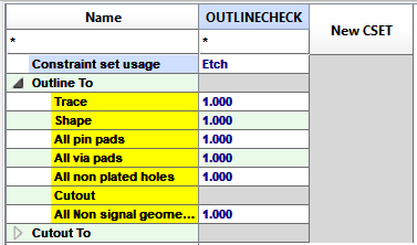
10. Left-click the “triangle” to the left of “Outline To” to expand the values and set the values to 1.0mm(Drag-select the cells and then type 1.0 and enter, or use the down-arrow, or Tab, key to move between the cells, the mouse click will work as well)
11. Left-click on Design / Annular Ring for Design for Fabrication
12. Left-click in the Referenced DFF CSet cell for Conductor / All and pick PadViaCheck from the drop-down
13. Left-click in the Referenced DFF CSet cell for Plane / All and pick PadViaCheck from the drop-down
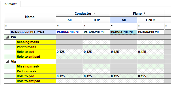
(The Pin values have been “opened” in the screen shot)
(If you don’t get the same view, use the View>Transpose from the menu to change it)
14. Left-click on Design / Outline for Design for Fabrication
15. Left-click in the Referenced DFF CSet cell for Conductor / All and pick OutlineCheck from the drop-down.
16. Left-click in the Referenced DFF CSet cell for Plane / All and pick OutlineCheck from the drop-down.
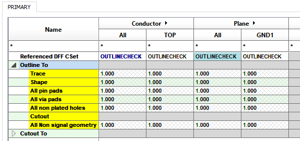
17. Left-click the Outline entry in Design for Assembly / DFA Constraint Set
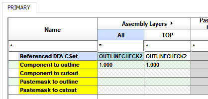
18. Left-click the “New CSET” cell and set the Name of the new check to OutlineCheck2 and left-click>OK
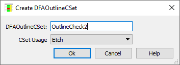
19. Set the value for Component to Outline to be 1.0mm
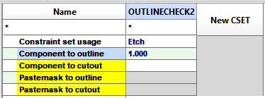
20. Left-click on Design / Outline for Design for Assembly
21. Left-click the Referenced DFA CSet cell for Assembly Layers / All and pick OutlineCheck2 from the drop-down.
22. Go back to the PCB Editor window and File>Save, Yes to overwrite the constraints.brd
Note that “arbitrary” values have been used for these Manufacturing constraints for the purposes of illustration, more reliable value would be provided by your fabricator / assembler.

End of Lab
All content Copyright 2022 Parallel Systems Ltd.