
All content Copyright 2022 Parallel Systems Ltd.
1. Start the PCB Editor and open placed.brd, if it is not already open.
2. Left-click the Colour icon and use Color / Visibility to turn ON the following classes and subclasses. You can leave your currently visible classes and subclasses as they are. (Change any colours, as required)
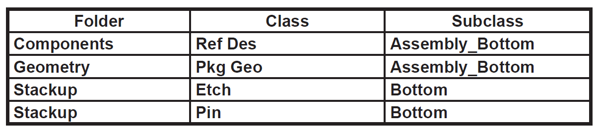
3. Left-click>OK to close the Colour Dialog form.
4. Select Edit>Delete from the top menu and left-click twice on U2 in the canvas.
(U2 is the DIP 24 pin package, left-click once to select, and again to confirm, delete)
5. Select Place>Components Manually from the top menu.
6. Left-click the box for component U2.
7. Left-click>Hide
8. Move the mouse to canvas and right-click>Alt Symbol and choose SOIC24 from the pop-up menu.
The package style changes to a surface-mount SOIC24.
9. Right-click>Mirror from the pop-up menu.
The part is mirrored to the bottom side of the design and the package style changes back to the original DIP24 (DIP763W46P254L3204H508Q24P) footprint.
10. Right-click>Cancel from the pop-up menu.
11. Select Setup>Design Parameters from the top menu and choose Design tab.
12. In the Symbol group (lower right), enable Mirror and then left-click>OK.
13. Select Place>Components Manually from the top menu.
14. Left-click the box to the left of U2.
15. Left-click the Hide button.
16. Right-click>Alt Symbol and SOIC24-PE from the pop-up menu
The package style changes to an SOIC24_PE.
17. Left-click to place U2 on the bottom side of the board.
18. Right-click>Done from the pop-up menu.
19. Select Check>Properties from the top menu.
The Show Property form appears.
20. Choose the ALT_SYMBOLS property from the scroll list.
21. Left-click>Show Val.
The Show window displays a list of part types that have alternate package styles in the current board design.
22. Left-click>Close in the Show window.
23. Left-click>OK in the Show Property form.
24. Select File>Exit from the Editor menu.
25. Select No to NOT save the design.
End of Lab
All content Copyright 2022 Parallel Systems Ltd.