
All content Copyright 2022 Parallel Systems Ltd.
Start PCB Editor from:
Start (Windows Icon) >Cadence PCB 17.4-2019>PCB Editor 17.4
The PCB Editor Canvas opens.
1. Select File>Open from the PCB Editor main menu.
2. If necessary, set the File Type for Board (*.brd)
3. Use the Browse button to navigate to the C:\OrCAD_Training\PCB_Designer_Advanced directory, select the rigid_flexi_stackup.brd file and left-click on Open
This lab will go through the creation of four flex zones as shown below:-
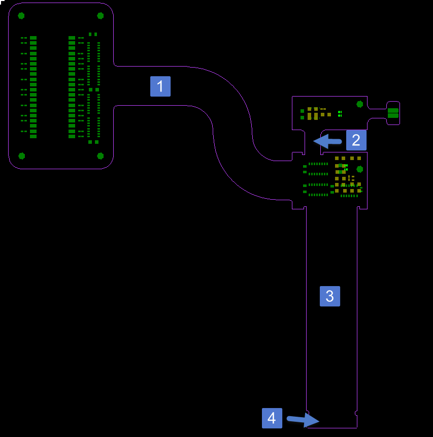
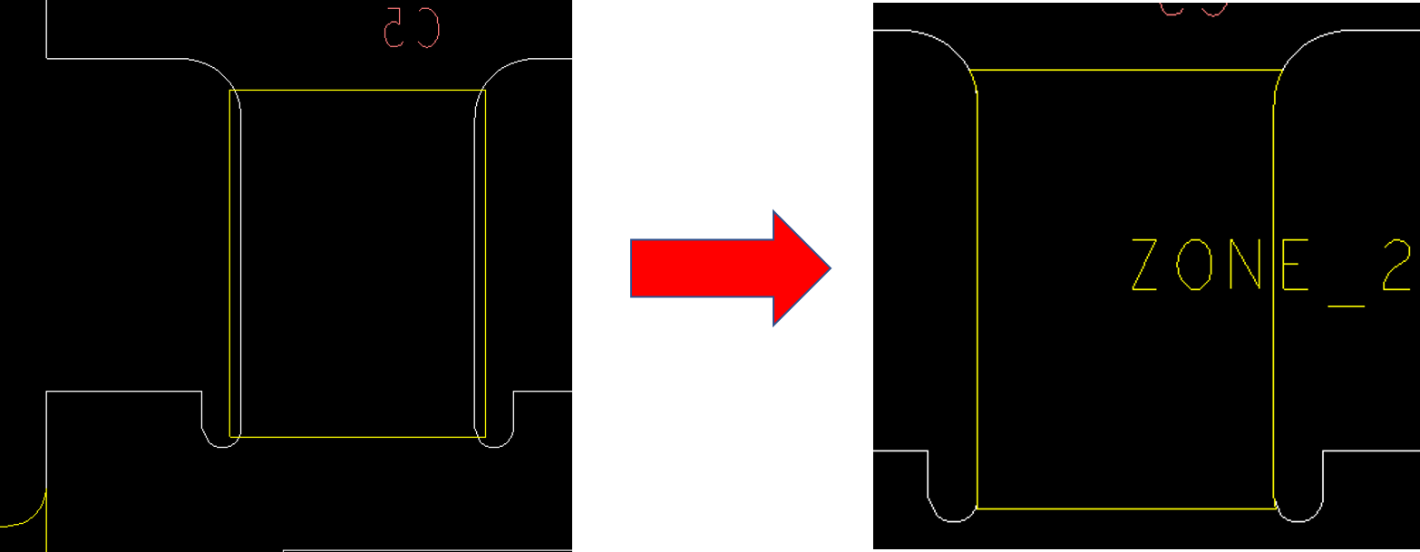
4. Start Zone creation from Setup>Zones>Create. In the Options pane the Zone data attributes are displayed. Change the Stackup dropdown from Primary to Flex1.
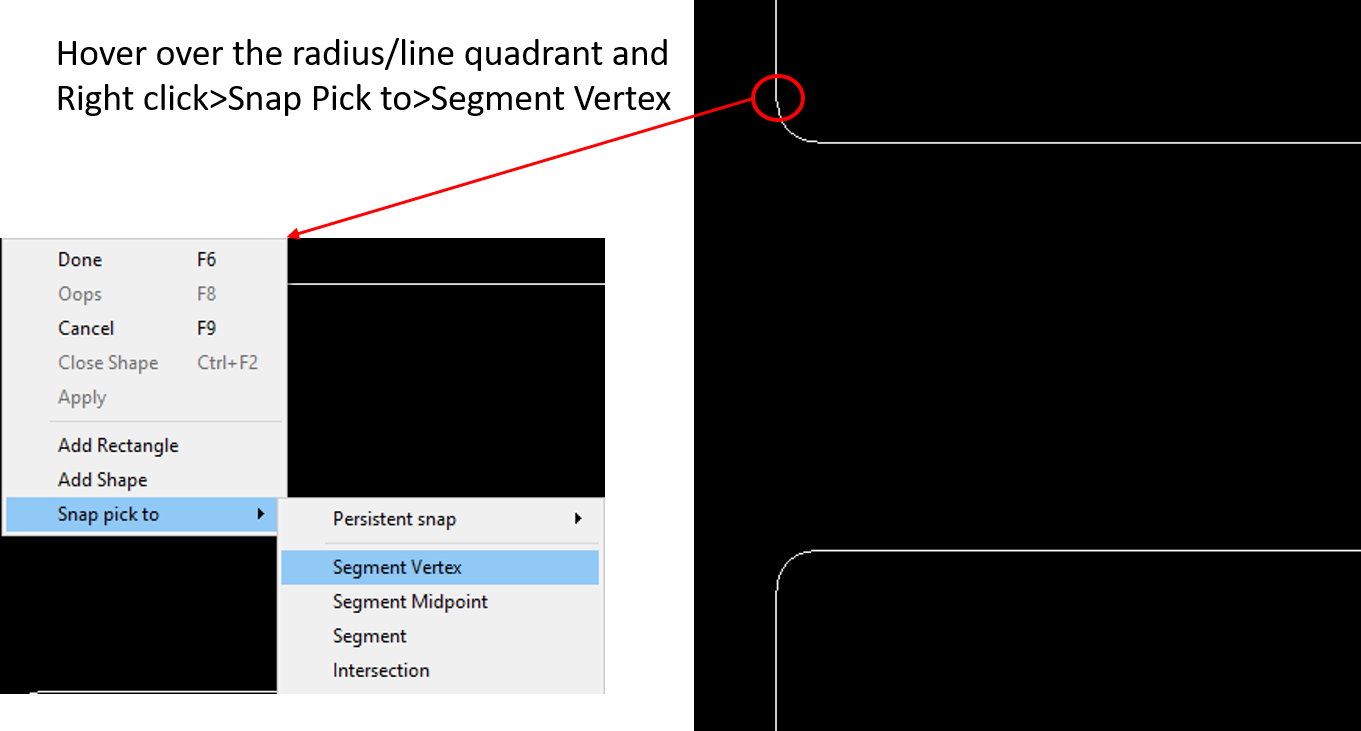
5. In the graphics window, use right click>Add Shape and add a shape following the guideline below. You can use the right click>Snap Pick to>Segment Vertex (on the radius edges) but you don’t have to be too precise as the boundary of your rectangle will snap to the design_outline. (You may need to right click>Close Shape to complete the shape definition)
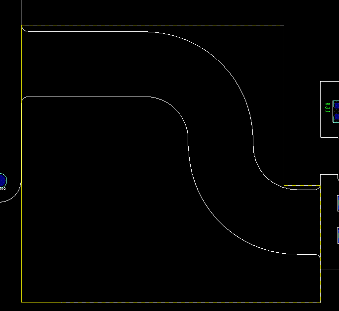
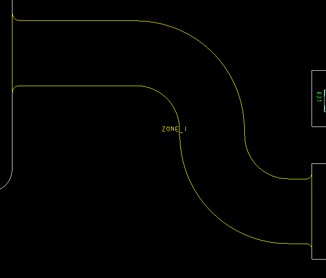
6. The completed zone should look similar to the figure below.
7. Go to the Options Panel. The zone name has incremented to the Zone_2. Change the stackup dropdown to Flex2 and draw the rectangle as shown below (right click>Add Rectangle).
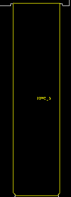
8. Go to the Options Panel. The zone name has incremented to the Zone_3. Change the stackup dropdown to Flex1 and draw the rectangle as shown below (right click>Add Rectangle).
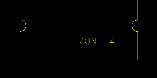
9. Finally, add Zone 4 referencing stackup Flex3. You can overlap Zone 3 during the create steps. It will then snap to be coincident with Zone 3’s edge.
Note: to modify the boundary after it has been created requires you to be in shape edit application mode. (Setup>Application Mode>Shape Edit). Go to the Options Panel and click Enable Zone Boundary Editing. You may adjust the boundary using the shape edit slide command. Note after you slide an edge it will snap to the Design Outline.
10. To verify the proper zone and stackup assignments, open Setup>Zones>Manage. The Zone Manager displays each zone placed in the design. The form displays the following information
Name – The identifying label of the zone
Stackup – The name of the referenced stackup defined in the cross section editor
Start Layer – The first conductor layer defined in the reference stackup (Read only).
Stop Layer – The last conductor layer defined in the reference stackup (Read only).
Constraint Reg – The associated constraint region name.
Room – The associated Room name.
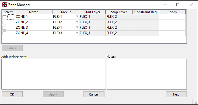
11. Zone names and stack-up references can be modified in the form. Change the Zone_3 stackup from FLEX1 to FLEX2.
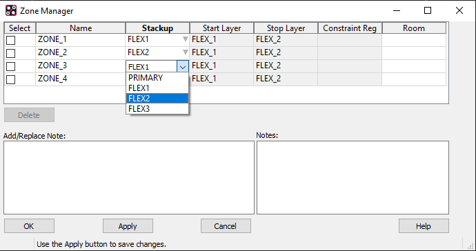
12. Select the Apply button located at the bottom of the form. Zone_3 now references FLEX2.
13. You can also change the name of a zone, select on the name field for Zone_4 and In the name field, enter CONN_ZONE then Apply. The zone is renamed to CONN_ZONE.
14. If you need to delete a Zone you can also do that in this form. Left Click the checkbox next to Zone_2 and then select the Delete button. Zone_2 is now removed from the design. Review the screenshot below to see these changes.
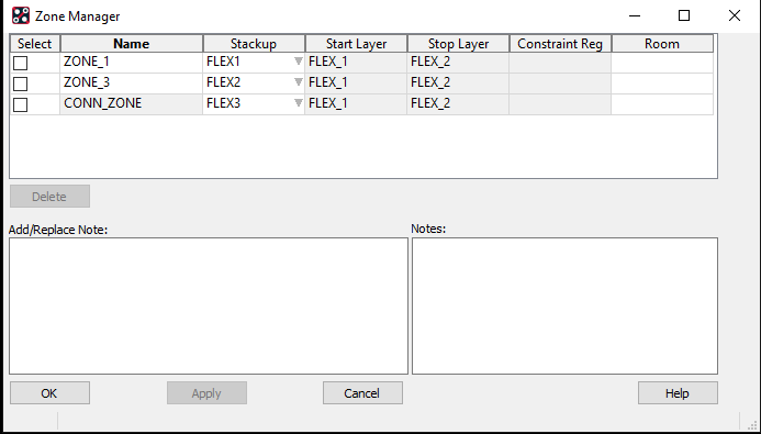
15. You can change the visibility of the Zone_Outline that have been added using Setup>Colors then the Rigid Flex folder.
Note: You can if required assign the Primary stackup to the main part of the PCB although this is not necessary since unassigned sections of the PCB will default to the Primary stackup. This can help though when generating cross section tables (covered in lab 12-4).
Note: By default, Route Keepouts are added automatically to the zones for the layers that are not part of the stackup for that zone. Go to Setup>Colors>Areas and turn on the Route Keepout areas layer by layer to see the result.
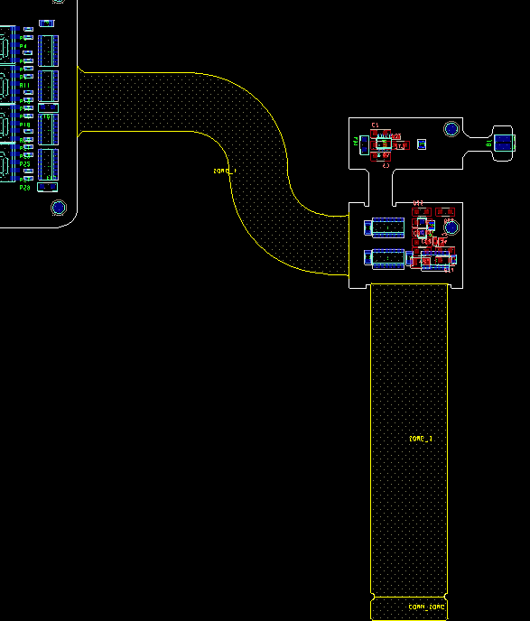
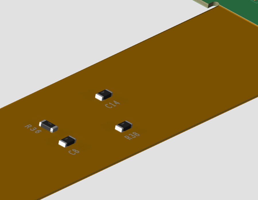
16. Go to the Visibility tab and turn on the layers Flex_1 and Flex_2. Notice how the parts that are placed in the middle of Zone_3 have dynamically been updated to be placed on layer Flex_2.
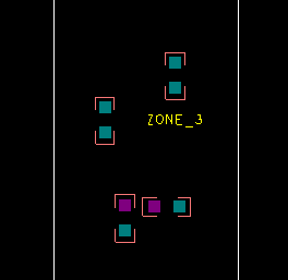
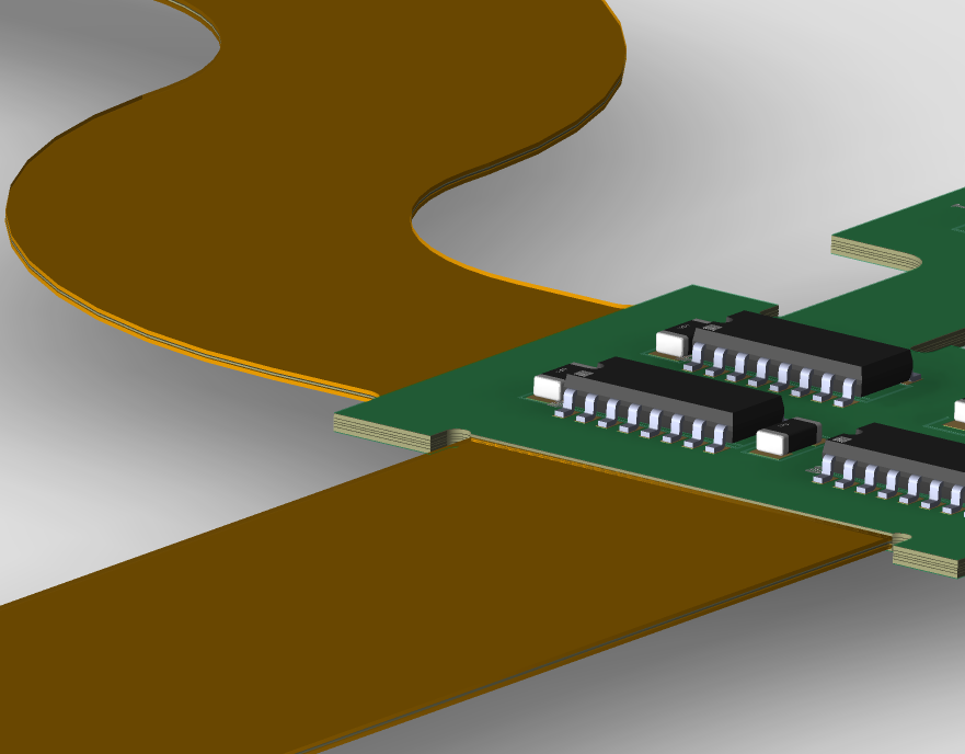
17. Invoke the 3D Canvas from either the 3D icon or Display>3D Canvas. You can use the mouse scroll wheel to zoom in/out, hold the middle mouse button down to pan and use the SHIFT + middle mouse button to spin the 3d View. Notice how the flex sections only show the actual thickness of the flexi. Also notice that the parts are placed directly on the flexi surface.
18. Close the 3D canvas and save the design as rigid_flexi_zones.brd.

End of Lab
All content Copyright 2022 Parallel Systems Ltd.