
All content Copyright 2022 Parallel Systems Ltd.
Start PCB Editor from:
Start (Windows Icon) >Cadence PCB 17.4-2019>PCB Editor 17.4
The PCB Editor Canvas opens.
1. Select File>Open from the PCB Editor main menu.
2. If necessary, set the File Type for Board (*.brd)
3. Use the Browse button to navigate to the C:\OrCAD_Training\PCB_Designer_Advanced directory, select the placement.brd file and left-click on Open
Notice that there are two IC’s, U12 and U13 that are placed off the left hand side of the board. We want to define some length rules for the DQ Netclass which will help us with ensuring that these nets are routed within a certain length.
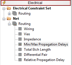
4. Open Constraint Manager and go to Electrical>Net>Routing>Min/Max Propagation Delay.
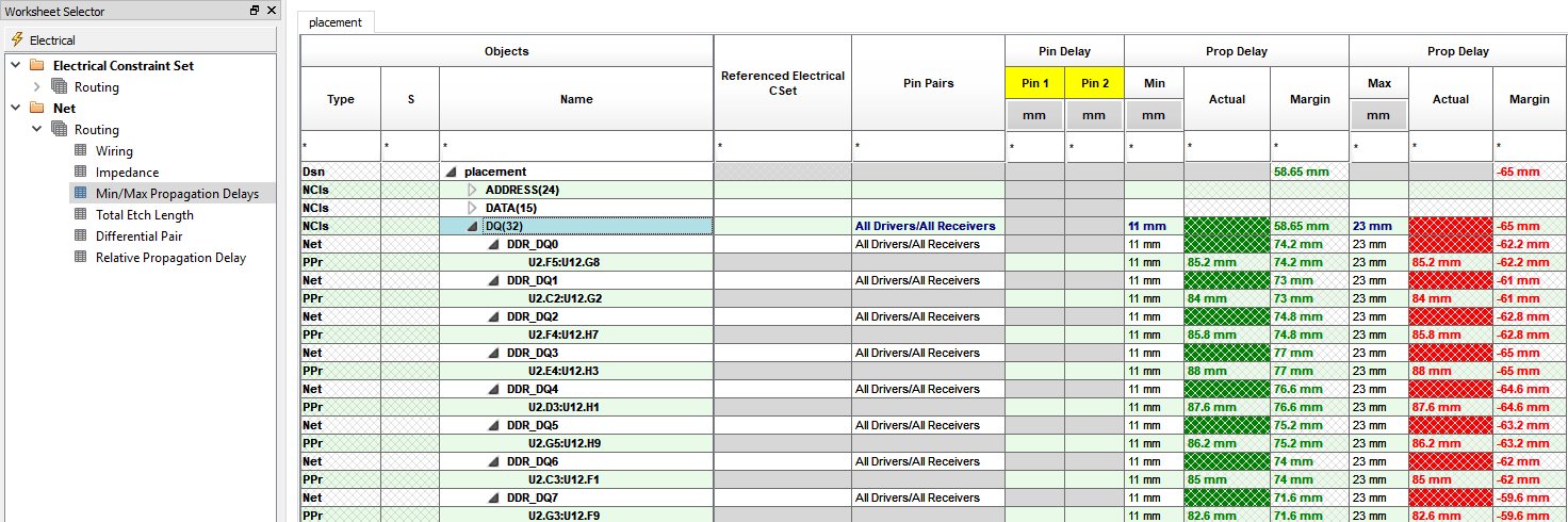
5. Select the + next to the DQ Netclass to expand it if required and enter a value of 11mm for MIn Prop Delay and 23mm for Max Prop Delay at the Netclass level (This will be applied to all members of the class) and should be similar to the screenshot below.
Minimize Constraint manager and return to the main PCB Editor canvas.
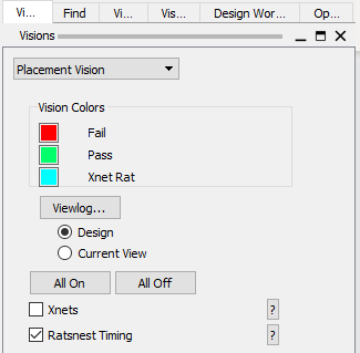
6. Use Display>Vision Manager to open the Vision Manager to select the Vision mode. This pane can be docked along with the other panes (such as Options or Find).
7. From the drop-down, select Placement Vision with a left-click. Enable Ratsnest Timing in the Options pane. You can also change the colours of fail and pass to suit.
8. Move the IC U12 using either Placement Edit Mode or Edit>Move and notice that the ratsnest items that are part of the DQ bus are displayed in Red meaning they fail the timing we defined in Constraint Manager. The remainder of the ratsnest will stay as the default colour – in this case yellow.
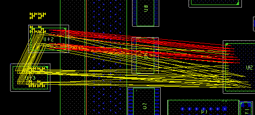
9. Move U12 closer to U2 and as you get closer and the ratsnest start to meet the constraint rules they change colour from Red to Green.
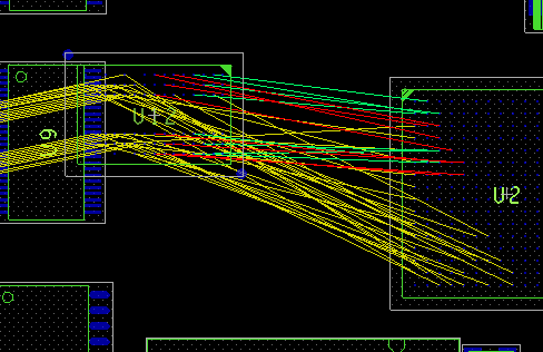
10. Once all the ratsnest associated with the DQ class have changed to Green place the IC down with a left click.
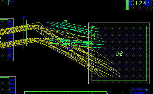
11. Repeat these steps and place U13. Your final placement should look similar to:-
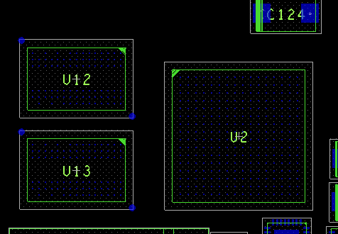
12. Open Constraint Manager and examine the worksheet. All the values should now be green – meeting your constraints.
13. The Placement Vision can be removed by setting the Visions drop-down to “No Vision” and the Visions form closed with the “X”

End of Lab
All content Copyright 2022 Parallel Systems Ltd.