
All content Copyright 2022 Parallel Systems Ltd.
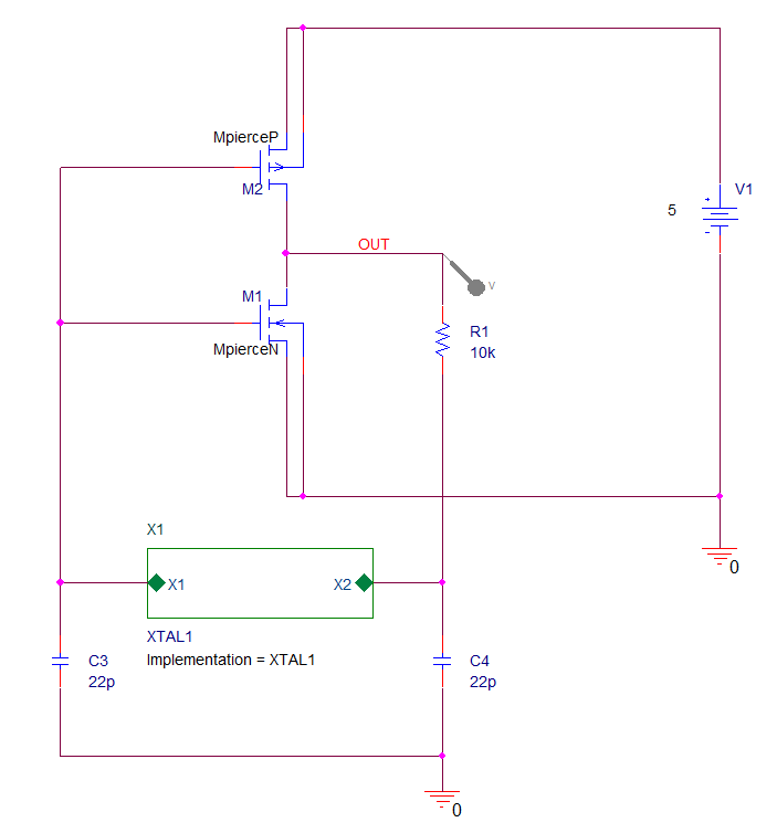
For the first part of this section, the circuit is a Pierce Oscillator.
1. Open the project called PierceOsc from the C:\OrCAD_Training\PSpice folder and Run the Simulation.
Note that the Probe Window result is a “flat line”, no oscillation.
The implementation for the XTAL1 block is the original high Q equivalent circuit, this is replaced in the XTAL2 definition of the block with a much lower Q (about 7) by reducing the inductor value to an equivalent amount and eliminating the capacitors.
2. Double-click on the “Implementation = XTAL1” text, edit the XTAL1 value to XTAL2 and left-click>OK. Run the simulation again and the circuit now oscillates.
3. Left-click on the V(OUT) trace name and press Delete to remove the trace, then Trace>Add Trace, select the I(X1.L1) trace name and left-click>OK to add the trace. Make a note of the peak value, about 350uA is precise enough for this exercise.
4. Return to the Capture window and Double-click on the “Implementation = XTAL2” text, edit the value to XTAL3 and left-click>OK. Double-click the “green block” to descend the hierarchy and then double-click on the L1 part to edit the properties, set a value of 350u for the IC property. Then Run the simulation again.
The circuit oscillates but the results are “not great”
5. Go back to the Capture window and select C3 and C4, window the parts, or left-click and control+left-click to select them both and then use Control+E to start the property Editor. Locate the IC property for the capacitors, set the value to 2.5 and then return to the schematic and Run the simulation again.
Note that, this time, the waveform looks a lot better.
The second part uses a switched mode power supply of dubious quality!
1. Open the project called converg3 from the C:\OrCAD_Training\PSpice folder
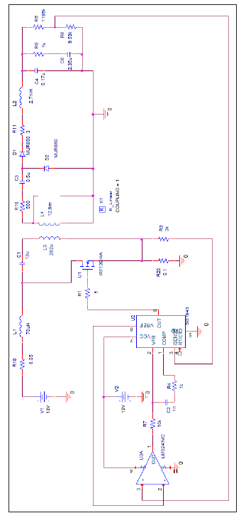
2. Examine the schematic provided below for reference.
3. Select PSpice>Edit Simulation Profile from the top menu to open the Simulation Settings dialog box.
4. Review the profile settings and run the simulation.
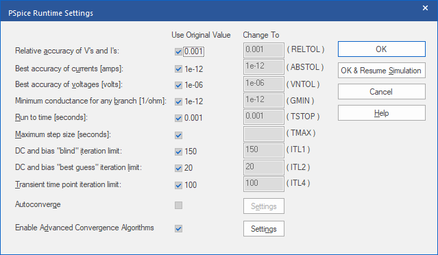
The PSpice Runtime Settings dialog box and a convergence error similar to the one that follows opens as the simulation pauses.
Note
The exact error message you receive may vary slightly.
5. Left-click>Cancel in the PSpice Runtime Settings dialog and close the Probe window and left-click>OK the paused simulation when asked.
6. Place a 1k snubbing resistor in parallel with L4.
7. Run the simulation again.
Although the error message changes, the simulation pauses again, and errors or problems still exist.
8. From the PSpice Runtime Settings dialog box, un-check the Use Original Value
check box for RELTOL and set its value to .01.
9. Left-click>OK & Resume Simulation to continue the simulation from where it left off.
If errors still exist:
10. Un-check the Use Original Value check box for Maximum Step Size and set it to 1e-12.
11. Left-click>OK & Resume Simulation to continue the simulation from where it left off.
Once again, there is a convergence error.
12. Un-check the Use Original Value check box for ABSTOL and set it to 1e-09.
13. Left-click>OK & Resume Simulation to continue the simulation from where it left off.
The simulation will still not run so we will try something else.
14. Completely close PSpice/Probe to clear out the simulation.
15. In Capture, edit the simulation profile.
16. Left-click Options on the left hand side it and left-click the AutoConverge under the Analog Simulation group.
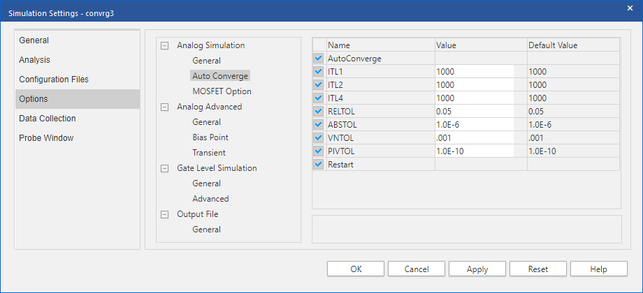
17. Left-click the AutoConverge check box.
18. Left-click>OK in the AutoConverge Options dialog.
19. Left-click>OK in the Simulation Settings dialog.
20. Run the simulation again. It should now run to completion.
Add a Voltage probe at the L2, C4, R9, R5 junction and observe the voltage waveform as the regulator starts.

End of Lab
All content Copyright 2022 Parallel Systems Ltd.