
All content Copyright 2022 Parallel Systems Ltd.
1. If necessary, start OrCAD Capture, or CIS, with a PSpice license.
2. From within Capture or in the Probe window, select File>New>Text File from the top menu.
3. Type in the netlist for the schematic below.
The title line should contain CLIPPER. (“* Clipper” for example)
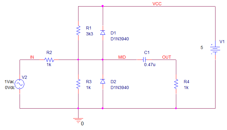
Note that the simulator only uses “scientific” values so, 3k3 will need to be 3.3k for the simulator.
For reference:
General form for a Voltage source is:
V<name> <(+) node> <(-) node> [ [DC] <value> ] [ AC <magnitude value> [phase value] ]
Parameters in square brackets [] are optional, parameters in angle brackets <> are required to specify the parameter value. (Don’t include any brackets, just type the values)
So: V1 VCC 0 DC 10 will represent a 10V DC source with positive on VCC and negative connected to the 0 node.
4. After entering the netlist description add a .Probe statement that contains no voltage or current statements.
5. Add a library call for nom.lib. A .LIB statement with no arguments can be used since nom.lib is assumed.
6. Add an AC sweep analysis specification. It will have the format:
.AC DEC 11 10 100meg
7. End the file with an .END statement.
8. Save the file as CLIP_NL.CIR in the C:\OrCAD_Training\PSpice directory.
9. Start Probe from Windows icon>Cadence PCB 17.4-2019>PSpice AD
(Or Alt-Tab to the Probe window if it is still running from previous simulations)
10. Choose File>Open Simulation from the top menu.
11. In the Files of Type field, left-click the pull-down and select Circuit Files (*.cir).
12. Locate clip_nl.cir, in the C:\OrCAD_Training\PSpice directory, and select it.
13. Left-click>Open.
14. The circuit file you entered displays. You can make any required edits directly in this window, no need to go back to Capture if you entered the text from there.
15. Choose Simulation>Run or use the simulate toolbar button to start the simulation. If the netlist syntax is correct, the Probe window opens on another tab, or check the output for syntax and typing errors.
If desired, you can examine the results and compare them to the output you received in Lab 4-1.
16. Add traces manually using Trace>Add Trace since markers are not supported from a text file.

End of Lab
All content Copyright 2022 Parallel Systems Ltd.