


OrCAD PSpice AD AA & Matlab SLPS Integration
Advanced circuit simulation and analysis for analog and mixed-signal circuits
OrCAD PSpice & Advanced Analysis technology, combines industry-leading, native analog, mixed-signal, and analysis engines
Powerful Simulation
Circuit Optimization
Unparalleled Waveform Viewing and Analysis
Enhanced Capabilities
Extensive Model Support
Open Architecture Platform
| PSpice AD Basic | PSpice Designer | PSpice Designer Plus | |
| Simulation capacity: 250 Nodes, 250 devices, 1M Transient, 10K AC / DC Sweep, limits |  |
||
| Simulation capacity: unlimited | |
|
|
| Analog Devices: all except BSIM 3.3, BSIM4, Magnetic Core, IGBT, Tlines, DMI | |
||
| Analog Devices: All | |
|
|
| Analog behavioural modelling | |
|
|
| Digital Devices: All | |
|
|
|
|
|
|
|
|
|
|
| Bias point voltages, currents and power display in Schematic | |
|
|
| Modelling Application in Capture | |
|
|
|
|
|
|
|
|
|
|
| Check Point restart | |
|
|
| Auto Convergence, Advanced Convergence and Speed Mode | |
|
|
| Interactive waveform viewer and analyzer | |
|
|
| Waveform: FFT | |
|
|
| Advanced tools: FRA, Core loss | |
|
|
| Performance Analysis | |
|
|
| Model Editor, Stimulus Editor, Magnetic Parts Editor | |
|
|
| Advanced Analysis: Smoke (Stress) | |
|
|
| Advanced Analysis: Optimiser, Sensitivity, Monte Carlo | |
||
| Advanced Analysis: Parametric Plotter | |
||
| PSpice - MATLAB Interface: Co-Simulation, Visualisation, Functions | |
||
|
|
|
|
|
|
|
|
|
|
|
|
|
|
|
|
|
|
|
|
|
|
|
|
|
|
|

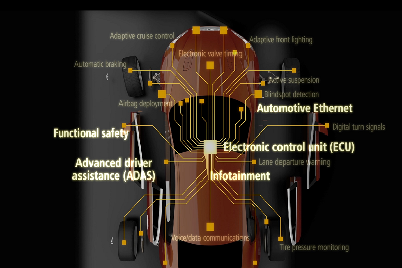
Today, more and more electronics from air bag sensors to safety and convenience features are being added to cars, revolutionizing automotive safety and electronics.
With new electronic technologies, there’s always a risk something will fail. Simulation of electronic circuits to verify their functionality and reliability based on component tolerances, temperature variations, and other parameters becomes critical. It is crucial for automotive companies to perform yield and reliability analysis through exhaustive simulations to ensure there are no recalls due to field failures.
Meeting Rigorous Automotive Requirements
Electrical systems are controlling more of a vehicle's reliability, performance, and environmental features—from airbags to all-wheel drive, GPS to advanced driver assistance systems (ADAS), and cameras to infotainment systems. Vehicles today are trending to more than 100 ECUs distributed under the hood and in the interior—creating a range of challenges in communication, coordination, power distribution, and other areas.
Common challenges include:

Connectivity Issues
Wiring connectivity issues that force the adoption of “drive-by-wire”

Distribution and hybrid drives
Power distribution and the introduction of hybrid drives, which are propelling miniaturization of very high-power densities in power electronics

Systems Modeling
Automotive embedded systems can be modeled at multiple levels of abstractions, including functional requirements, hardware architecture, and software requirements leading to final implementation

Mixed-signal simulation
The number of sensors in automobiles have been increasing at an exponential level from tire pressure sensors to oxygen level sensors, etc. All of these sensors are mixed-signal sensors with digital control loops requiring the capability of mixed-signal simulations

Virtual prototyping
Faster time to market by verifying the hardware and software integration is tested way in advance before building the hardware

Early software validation
Validating how the complete system will function per specification in software can significantly reduce cost of actually building the hardware and then addressing any field failures and/ or recalls

"Whether you’re prototyping simple circuits, designing complex systems, or validating component yield and reliability, OrCAD PSpice technology provides the best, high-performance circuit simulation to analyze and refine your circuits, components, and parameters before committing to layout and fabrication"
Applications of power electronics extend across almost every industry ranging from consumer, to high-end space and defense application segment, all having their end products bound by the same goal of reliability, efficiency, simplicity, performance, control and unique set of challenges to accurately characterize and simulate.
PSpice® technology offers mixed-signal simulation and system-level analysis capabilities across different levels of abstraction across low- to high-power applications, including electric vehicles to data centers, to wearables, renewables, and the power grid. Known for its accuracy and high performance in power supply simulation technology as well as the ability to integrate with OrCAD® capture and Allegro® solution, PSpice simulation program makes power supply analysis simple.
Looking beyond the Power Supply Design Limitations
Worried about environmental regulations, heat dissipation, power supply stability, or cost and form factor? Whether you’re designing switch model power supply (SMPS), power amplifiers, invertors, or traditional linear voltage regulator circuits, you need to overcome the common challenges of:

High power
Difficult to characterize accurately in the lab, requires models for high voltage high power IGBT Module such as power semiconductors

“Multi-Rate” simulation problems
Requires 1000’s of input-signal cycles to achieve synchronization

Magnetic Component Requirements
Requires special models for magnetic components involving “nonlinear magnetics,” etc.

Low-Power Design
Testing the performance limits

Power Dissipation and Thermal design
Power Dissipation and Thermal design

Unified Design Environment
Drive your PCB layout from simulation results to improve reliability to optimize cost and size
OrCAD PSpice® Designer provides a single tool for system modeling and performing ECU and ECU-to-ECU simulations. PSpice simulation software can help users verify performance issues, complete risk assessments, and identify integration problems before hardware freeze. Avoid production failures or late-stage design changes with the ability to simulate and evaluate automotive ECU design blocks at any level of abstraction. Based on your speed and accuracy requirements, full system-level analysis can be performed incorporating the complete drive-by-wire design with mixed-signal control loops and software control. With our SPICE circuit simulator, you can:
Minimize Design Cycles

Minimize extra design and prototype cycles
Improve Performance

Improve design quality and performance
Automate Design Tasks

Automate as many of the tasks as possible
Avoid Problems

Avoid problems, from field failures to manufacturing tolerance variations to power dissipations
Perform Advanced Analysis

Perform advanced analysis by incorporating user-defined post-processing algorithms
What is Internet of Thing (IoT) ?
While everyone has a different outlook on Internet of Things, there is a common agreement to the NEED of sophisticated mixed signal verification tools with ties to systems-level tools for full functionality testing. With the downsizing of connection and technology costs,there is a significant increase in devices with built-in WiFi and sensors with smartphone usage.
Devices like sensors, actuators and recently invented monitoring and control devices—which help in analyze and optimize our world—are creating a perfect storm for IoTs used in power supply and automotive markets. PSpice® technology, with its large simulation library and high performance (switching at high speed) provides the ultimate solution for the IoT market.
Addressing the demanding needs of IoT and Innovation
Business Insider Intelligence estimates that nearly $6 trillion to be spent on IoT solutions over the next five years, with other research firms estimating 50-100 billion devices to be connected to the internet in the same timeframe. This sets high expectations in this increasingly competitive market for new package and board technologies to satisfy the growing hunger for innovation leading to successful IoT products. How do you handle the common needs for the electronic components such as the ones with the smallest form factor like wearables and ultra-low power to larger SoC designs?
Challenges

Power
In IoT devices, power is very critical since the devices need to run for days/weeks/months/years. Simulations can help you minimize power consumption in these devices

Mixed-signal challenges
Analog and digital integration, interface and communication standards, and the combination of sensor systems has increased the complexity since it includes analog mixed signal, RF-wireless and digital microcontrollers among chip, package and board

Design form factor limitations
IoT products are driven by the need for the smallest form factor (think wearables) and ultra-low power (for longer battery life) that require advanced simulation and analysis

Model availability
Customers need models supporting multiple different abstraction levels so that they can trade off performance vs. accuracy. PSpice technology supports abstraction levels ranging from circuit level, to behavioral to C/C++/SystemsC
Integration
System level and IC integration

Go to Market
Improve design reliability, reduce cost, increase productivity, and optimize your design using the advanced analysis features of PSpice technology
The Internet of Things brings about a transformative shift in the economy similar to the time of the introduction of the PCs creating new business opportunities for a variety of applications. PSpice analog and digital circuit simulator helps you with:
Model development

Leverage Model Editor and parametric extraction algorithms to design magnetic components using commercially available cores, wires grades and different insulation materials
High performance
Improve performance by leveraging models from high-level abstracts to implementation models
Accuracy and better reliability

PSpice Advanced Analyses helps reduce design cost, improve productivity, increase manufacturing yield, improve overall reliability, and is the de facto standard for accuracy
Mixed-Signal simulations
IC and behavioral constructs for macro modeling for PCB simulation
Flexibility

Analog, mixed-signal and system-level simulations can all be performed from the same environment

Analog Design and Simulation Using OrCAD Capture and PSpice
2nd Edition
The powerful waveform analysis capability of PSpice gets another boost by enabling simulation results exporting to MATLAB. Now PSpice users have complete and seamless access to MATLAB plotting capabilities, can view PSpice simulation results in MATLAB, and can customize waveform processing on export.
Here are some example videos sharing with you how to use PSpice SLPS to perform system-level simulations that include realistic electrical models of actual components.
PSpice SLPS Introduction
This video demonstrates how to integrate system and circuit design with the Simulink-PSpice Interface (SLPS).
PSpice SLPS Demo Overview
This overview video demonstrates how to integrate system and circuit design with the Simulink-PSpice Interface (SLPS).
PSpice SLPS Overview
Learn how PSpice SLPS enables co-simulation for complete system model for test and verification and helps identify errors early in the design process.
PSpice SLPS RC Circuit
This video demonstrates how to integrate system and circuit design with the Simulink-PSpice Interface (SLPS) using an RC Circuit.
PSpice SLPS DC Motor
This video demonstrates how to integrate system and circuit design with the Simulink-PSpice Interface (SLPS) using a DC Motor.
PSpice SLPS Power Window
This video demonstrates how to integrate system and circuit design with the Simulink-PSpice Interface (SLPS) using Power Window.