
All content Copyright 2022 Parallel Systems Ltd.
1. Edit the Buffer circuit to look like the circuit that follows.
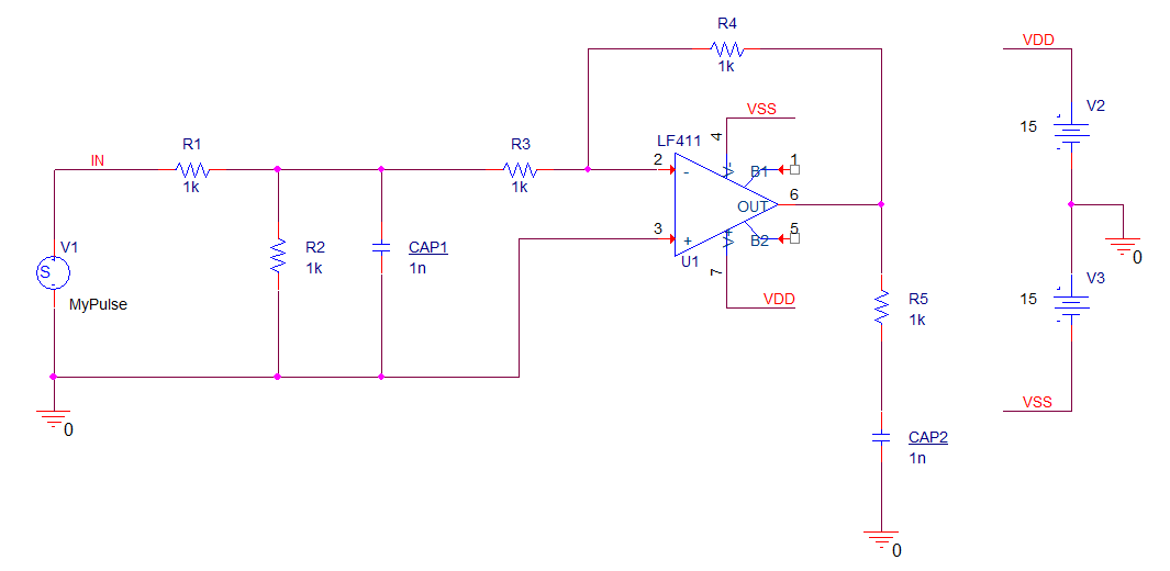
The additional symbols needed are LF411, and VDC. You will need to edit the value of the Capacitor reference designators, don’t worry about the resistor references, and check the component values, delete the OUT net alias.
You may need to configure Opamp.olb in order to place the LF411.
Also notice that the LF411 has the inverting input at the “top” and that the supply pins are also inverted. (flipped vertically)
2. Verify settings for the transient analysis profile, run 5u and ensure the Pulse stimulus file is configured in the profile.
3. Run the simulation.
4. From the Probe window, use Trace>Add Trace or left-click the Add Trace toolbar icon to open the Add Traces window.
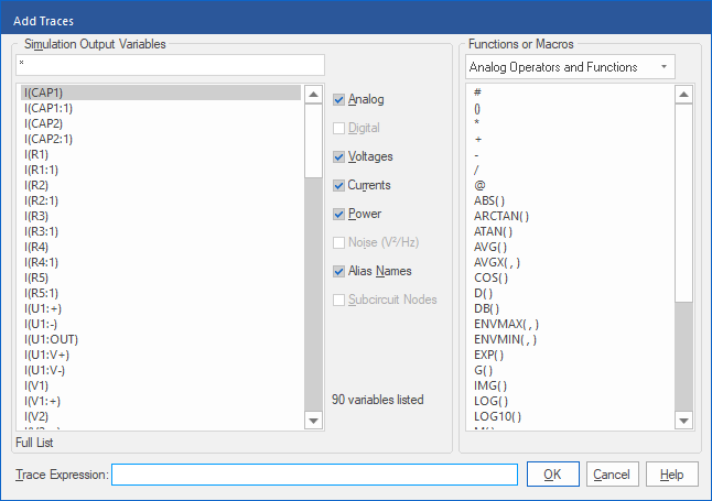
5. Left-click I(CAP1) and then left-click>OK to add the trace.
6. Select Plot>Add Y Axis from the Probe window top menu, to add another Y axis
7. Use Add Trace again and left-click I(CAP2) and left-click>OK to add the trace.
8. Double-click the Y-axis label 1 to open the Axis Settings dialog.
9. Enter CAP1 Current in Axis Title field.
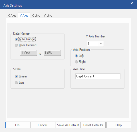
10. Select 2 from the Y-axis list.
11. Enter CAP2 Current in the Axis Title field.
12. Left-click>OK to save changes and close the dialog.
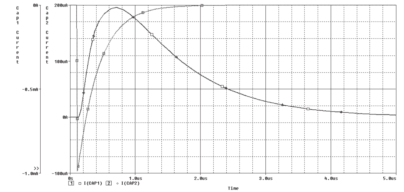
The Probe display resembles the following graphic.
Note
The first Y-axis is moved to the far left. The “>>” symbol points to the current axis. Any activities to change the title, range, or other settings are applied to the current axis. Left-click the desired axis to make it the current axis.

End of Lab
All content Copyright 2022 Parallel Systems Ltd.