
All content Copyright 2022 Parallel Systems Ltd.
Reference Schematic:
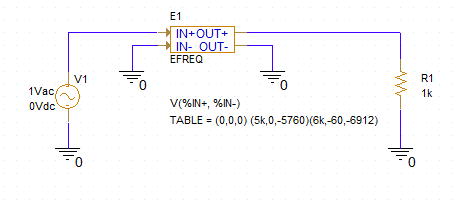
This circuit is a simple lowpass filter implemented using a frequency lookup table.
The input to the frequency look-up table is the voltage at node IN, the output is the output on node OUT.
The table values describe a lowpass filter with a response of 1 (0 dB) for frequencies below 5kHz and a response of .001 (-60dB) above 6kHz. The phase lags linearly with frequency.
The delay (phase wrap) is necessary so that the impulse response is causal; that is, so the impulse response has no significant real components before time zero.
1. Create a New Project based on the empty template
2. Open the schematic page and place and connect the symbols needed in the circuit: VAC, 0, EFREQ and R.
3. Check the voltage for V1 is 1V, the default for a VAC part.
4. Double-click on the EFREQ symbol to edit the properties.
5. Locate and select on the TABLE property.
6. Edit the value for the TABLE property to read:
(0,0,0) (5KHz,0,-5760) (6KHz, -60,-6912)
7. Left-click>Apply.
8. Left-click>Display, left-click>Value Only
9. Close the property tab
10. Set up a linear AC simulation profile with 101 points, starting at 1k and ending at 10k.
11. Left-click>OK
12. Select PSpice>Markers>Advanced from the top menu.
13. Select dB Magnitude of Voltage from the list.
14. Place the marker on node OUT.
15. Run the simulation and view the results in the Probe window.
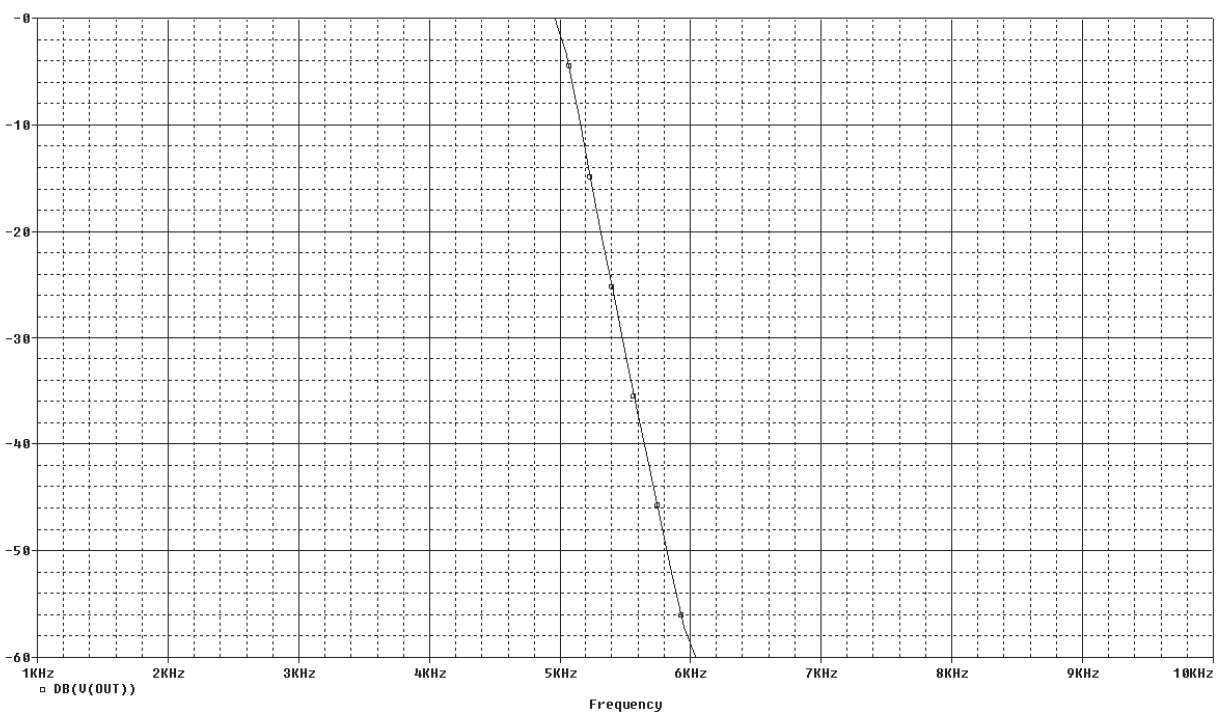
You can see that the response is as expected. Below 5k the response is 0dB and above 6k the response is -60db.

End of Lab
All content Copyright 2022 Parallel Systems Ltd.