
All content Copyright 2022 Parallel Systems Ltd.
1. Open the PSpice Model Editor by going to:
Windows icon>Programs>Cadence PCB Utilities 17.4-2019>PSpice Model Editor 17.4
2. Select Capture for the Design Entry Tool and Done if prompted
3. Choose File>New to start a new library.
You will name the library when you save it at the end.
4. Choose Model>New to begin creating a new model.
5. Type UF180 in the Model Name field.
6. Left-click the Use Device Characteristic Curves option.
7. Check that Diode is the selected From Model value.
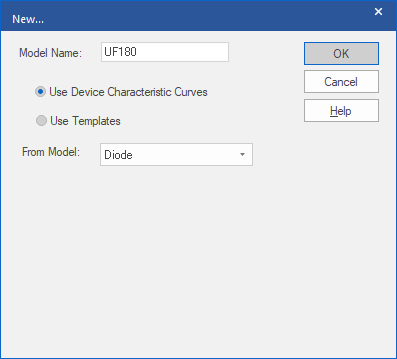
8. Left-click>OK.
The Model Editor opens. The Model Editor includes the following five tabs:
• Forward Current
• Junction Capacitance
• Reverse Leakage
• Reverse Breakdown
• Reverse Recovery
To define your new model in this exercise, you will enter new data values for each tab category. A sample data chart is provided for each tab. After reviewing a sample data chart, you will be ready to input values.
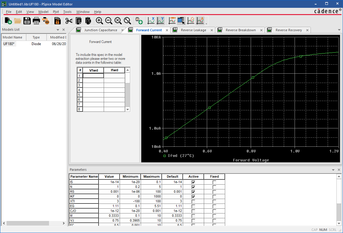
9. Select the Forward Current tab.
Notice the blank input fields for the Forward Current data points.
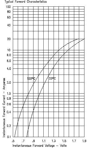
Note: Enter the values from the tables provided, there is no need to read the values from the graphs, these are just included for reference.
The next graphic provides the chart used to extract the Forward Current data points.
10. Enter data points as listed in the next graphic to define the Forward Current.
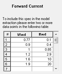
11. After entering all of the points for Forward Current, left-click the Junction Capacitance tab.
The next graphic that follows provides an example of a chart used to extract the Junction Capacitance data points.
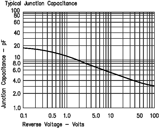
12. Enter the following data points to define the Junction Capacitance.
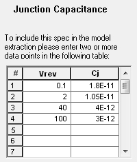
13. After you have entered all of the points for the Junction Capacitance curve, left-click the Reverse Leakage tab.
The next graphic that follows provides an example of a chart used to extract the Reverse Leakage data points.
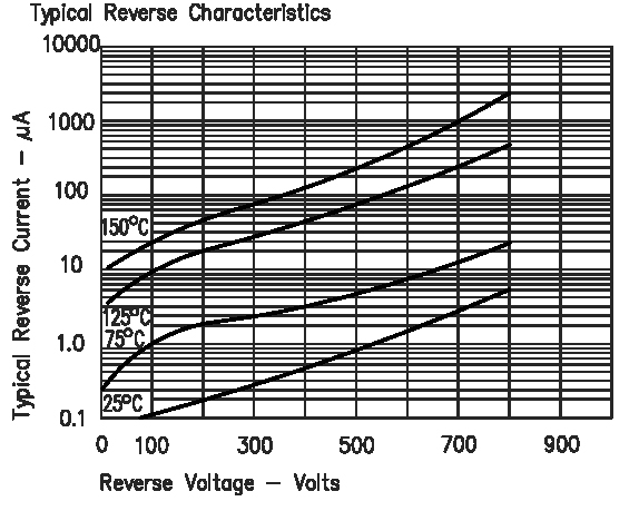
14. Enter the data points from the next graphic for the 25 degree C curve.
Typically, only a single point is fitted near the maximum reverse voltage.
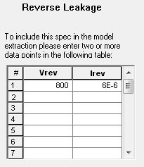
15. After you have finished entering the data point, left-click the Reverse Breakdown tab.
The next graphic that follows provides a sample chart you can use to extract values for Reverse Breakdown.
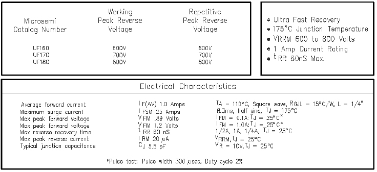
16. For the UF180, Vz is 800V.
17. Enter 800 in the Vz field.
18. Enter 2e-5 in the Iz field.
19. Enter 1 in the Zz field.
(Zz is not shown on the data sheet, this data would need to come from the part vendor)
20. Left-click the Reverse Recovery tab.
21. Enter 6e-8 into the Trr field.
22. Enter 0.25 in the Ifwd field.
23. Enter 2e-8 into the Irev field.
24. Enter 100 into the RI field.
You will often need to contact the vendor for this data.
You have completed the data entry for this device.
25. Choose Tools>Extract Parameters or left-click the toolbar button. 
The picture that follows shows the Reverse Leakage curve does not fit very well.
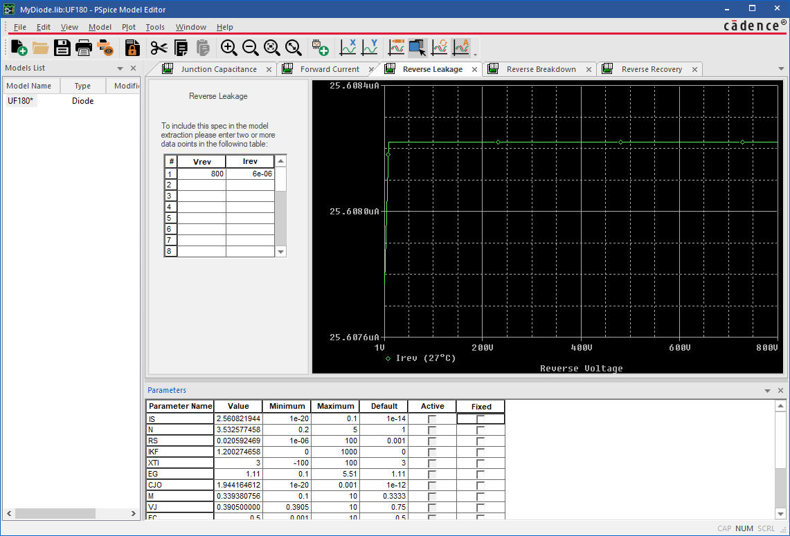
26. To improve the fit, edit the IS parameter. Decrease its value by one order of magnitude.(Expand the column that displays the data to see the entire value before attempting to edit the value)
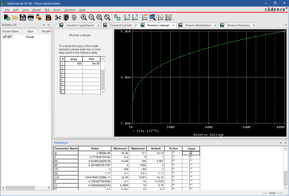
27. Left-click the Fixed column check box to freeze the IS parameter.
This prevents the IS parameter from changing as the extraction process is rerun.
28. Left-click the Extract toolbar button to extract the model parameters.
The next graphic that follows, shows an improved reverse leakage curve.
29. Choose File>Save As and save the file to MY_DIODE in the
C:\OrCAD_Training\PSpice directory.
30. Close the Model Editor and reopen it.
31. Choose File>Model Import Wizard…
32. Left-click the upper Browse button in the dialog.
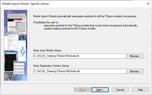
33. Select My_diode.lib and left-click>Open.
The library file is selected.
34. Complete the remainder of the dialog to create a part library. (use Next>)
35. Left-click>Finish.
A part library is created as a status dialog box opens.
36. Left-click>OK to close the status dialog box.
37. Close the PSpice Model Editor.
38. Create a new project to test the diode, enter a unique name for the project and base it upon the empty project template.
39. Create a simulation profile.
40. Left-click Configuration Files on the left hand side.
41. Left-click Library in the Category section on the left.
42. Left-click the upper Browse button and navigate to the OrCAD_Training, PSpice directory.
43. Double-click on My_diode.lib to select it and place it in the Filename field.
44. Left-click>Add to Design to make My_diode.lib visible to the current design.
(You could have left-clicked Add as Global to make it visible to every design that is opened or created.)
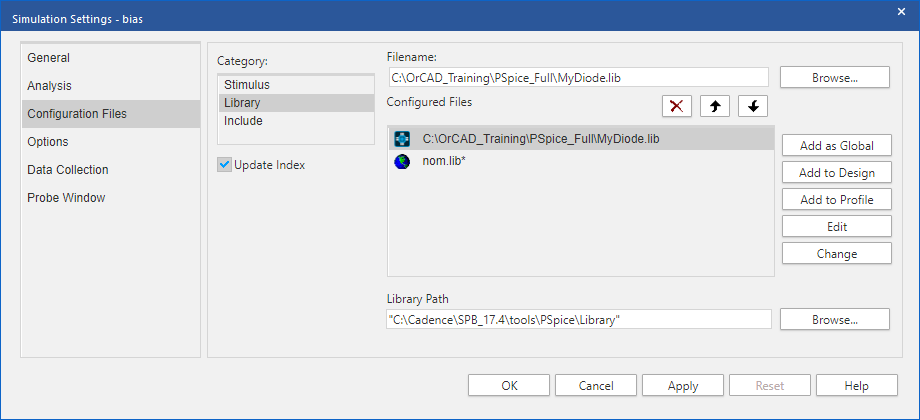
45. Left-click>OK to close the dialog.
46. Open the Place Part dialog using your preferred method.
47. Left-click>Add Library and navigate to the training directory.
48. Double-click on My_diode.olb to configure the library.
49. Select the UF180 part and place it on the schematic page.
Your new model is now configured. It has an associated graphic and is ready for use in a design.
50. Complete a circuit with a DC (VDC) source and a low value resistor to forward bias the diode and a 0 reference node.
51. Edit the Simulation Profile and configure a DC sweep of the voltage source from, say 0 to 10V in 10mV steps.
52. Left-click>OK to close the simulation profile.
53. Place a voltage marker on the anode of the diode and run the simulation to get the forward voltage displayed.

End of Lab
All content Copyright 2022 Parallel Systems Ltd.