
All content Copyright 2022 Parallel Systems Ltd.
1. Use the ABM VCO example from the previous lab, reopen the project if you closed
it.
2. Use Place>Part and add the library function.olb from the C:OrCAD_Training\PSpicelibrary\PSpiceadvanls directory.
3. Select the BEHAV_GEN part from the function library, place this part and connect it to a load resistor, similar to the arrangement shown below:
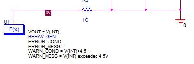
This resistor just provides a DC path for the output of the part.
(The circuit is laid out like this to reduce the size of the screen shot, any valid circuit arrangement that provides the BEHAV_GEN node a path to 0 will work)
4. Set the properties for the part as follows:
VOUT set to V(INT)
WARN_COND set to V(INT)>4.5
WARN_MESG set to V(INT) exceeded 4.5V
5. Run the simulation again
Look in the Messages Window, see that the warnings have been issued for V(int) exceeding 4.5V, in this case every 50ns since this is the Maximum Step Size setting.
Note
If you set an Error Condition, the simulation will halt when the error condition is encountered. Also, the Message Window has a limited number of messages but all messages are written to the Output File.

End of Lab
All content Copyright 2022 Parallel Systems Ltd.