
All content Copyright 2022 Parallel Systems Ltd.
1. If you have closed the Probe window for the buffer circuit, reopen it and display the PW(I(CAP2)) trace.
2. Select Window>Display Control from the top menu to open Display Control.
3. Left-click the Templates tab.
4. Type My_PW in the New Name text box.
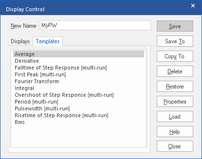
5. Left-click Save To which opens the Save Plot Window Template – Step 1 of 2 dialog.
6. Enter a description of the measurement. This description can be anything you want as shown in the following picture.
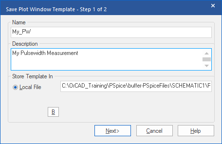
7. Left-click>Next to open the Save Plot Window Template – Step 2 of 2 dialog.
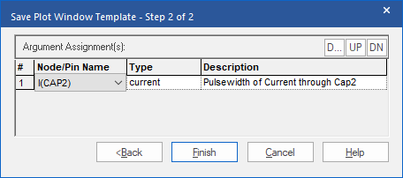
8. Select Current from the Type drop down box. (This will likely be the only selection)
9. Type a description for the function in the Description field. This will display in
Capture when you are placing markers.
10. Left-click>Finish to end creating the Plot Window Template. This will return to Display Control.
11. Left-click>Close to close the dialog.
12. Close the Probe window.
13. Return to the Buffer schematic.
14. Select PSpice>Markers>Plot Window Templates…. from the top menu
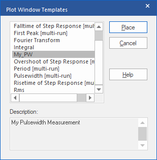
15. Select My_PW from the list.
16. Left-click>Place and attach the marker to the top pin of CAP2.
17. Select PSpice>View Simulation Results from the top menu.
18. Left-click>OK in the Available Selections dialog.
You should see the same results as in the second lab.

End of Lab
All content Copyright 2022 Parallel Systems Ltd.