
All content Copyright 2022 Parallel Systems Ltd.
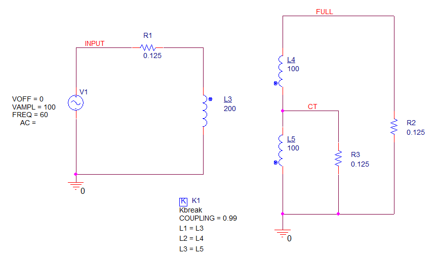
1. Using the same circuit as in the last lab, replace the K_Linear symbol with Kbreak.
2. Configure the Kbreak L1-L3 properties as they were for the K_Linear (L1=L3, L2=L4, L3=L5).
3. Edit the Inductor values, inductance needs to be turns.
4. For Coupling, use the default .99.
5. Change the values of R1, R2 and R3 to 0.125.
6. Run the simulation and examine the results in the Probe window. The core model will now be saturating, no longer a sine wave at the outputs.
Optional exercise
Return the circuit to the original linear configuration, use the K_Linear coupling part and set the primary inductance back to 10mH and the secondaries to 2.5mH, re-run the simulation and check the secondary voltages for these settings.
There are also specific centre-tapped symbols in the Breakout library, breakout.olb:
Xfmr_Nonlin/Ct-Pri, Xfmr_Nonlin/Ct-Pri/Sec, and Xfmr_Nonlin/Ct-Sec.
(There are similar Linear equivalents in the Anl_misc.olb)

End of Lab
All content Copyright 2022 Parallel Systems Ltd.