
Starting a PSpice simulation project in OrCAD Capture
Start Capture, or Capture CIS, with a license that includes PSpice, and use File>New>Project from the main menu.
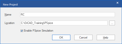
Name the Project, set the Enable PSpice Simulation Option and specify a location. Starting a Project with “Enable PSpice Simulation” set flags the project for simulation and attaches some of the fundamental libraries used for PSpice simulations. (PSpice Simulation may be enabled for the project after the project has been started by creating a Simulation Profile but the project may need some editing to ensure that the circuit uses parts setup for PSpice simulation)
After a left-click>OK, the project templates are listed.
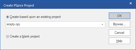
Capture can start a new PSpice project from a supplied template from the installation, which includes an “empty” project, or from an existing PSpice project using the Browse.
Once Capture starts, the PSpice toolbar will be enabled.

This is some confirmation that the project has been created correctly and enabled for PSpice simulations.
PSpice Libraries
The Libraries used for PSpice simulations are separated in the installation because they have some additional properties to specify the simulation models and map between the Model and the Schematic Part. It is possible to add these properties to your own libraries to make a set of “unified” libraries, if required. Also, not every component is suitable for simulation with PSpice, some models are simply not available and some large, complex, components, like FPGAs and Processors, would be inefficient to simulate, even if the vendor made a model available.
Any component without the necessary properties for simulation will simply be ignored when the simulation runs.
There are about 40,000 components provided in the PSpice libraries in the installation. (The graphical libraries are in <installation folder>tools\Capture\library\PSpice)
These obviously does not cover every component for which a SPICE model is publicly available but they provide a good starting point. Many more SPICE models are available from component vendors, usually freely available from the web sites.
Creating the Schematic
Common actions in Capture have three ways to activate them, a menu, a shortcut key and a toolbar icon.
For Placing Parts: Place>Part from the menu; “P” or “p” shortcut key; Place Part icon 
For Adding Wires: Place>Wire from the menu; “W” or “w” shortcut key; Place Wire icon 
For Adding Net Aliases (to override the default Net Name): Place>Net Alias; “N” or “n” shortcut key; Place Net Alias icon 
For Adding Buses: Place>Bus from the menu; “B” or “b” shortcut key; Place Bus icon 
Place>Part will open the Place Part dialog, docked to the right.
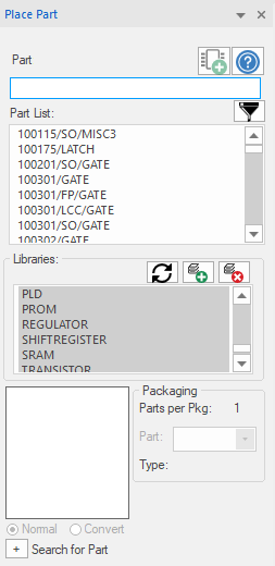
Use the Part section to specify the library Part required. The Part List will scroll so that the last item that is visible in the Part List will match the characters in the Part box, as they are typed. And a preview of the selected part will be shown.
The Libraries group has the selected libraries with a blue background, typically all of the libraries are selected. The icons in the Library group, reading left to right, are Refresh, Add Library, Remove Library. Adding, or Removing, Libraries only affects the configuration and not the library files themselves. To select all of the Libraries in the list, left-click in the list of libraries and press CTRL+A.
Left-click the “+” for “Search for Part” to search the OLB files in a location for parts.
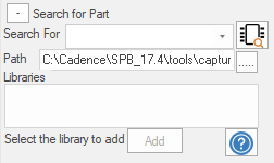
Type the required Part in the “Search For” box, “wild-cards”, like *, can be used, set the Path to search and left-click the  icon to get the search results.
Once a Part, or Symbol, is attached to the cursor for placement, it can be: Rotated with the “R” or “r” key; mirrored Horizontally, “H” or “h” key; mirrored Vertically, “V” or “v” key before placement. These keys can also be used after placement with the Part, or Symbol, selected.
Note that all nodes in the circuit must have a DC path to the 0 node and a special 0 symbol is used for this purpose from the Place>Ground menu.
Editing Properties
Part Properties can be edited by selecting the Part in the Schematic and right-click>Edit Properties, or by double-clicking on a Part.
All content Copyright 2022 Parallel Systems Ltd.