
All content Copyright 2022 Parallel Systems Ltd.
1. Create a new project named buffer, after OK, use the Browse for “Create based upon an existing project” and select the RC.opj in the C:\OrCAD_Training\PSpice directory.
2. Open the Schematic page, Page1 for the design and replace the DC source with a Vstim source using Place>Part.
3. Double-click on the Implementation property and change the value to MyPulse, tidy up the display with a “Value Only” setting and left-click>OK to set the value.
4. Edit the RC_DC simulation profile to configure a Transient Analysis with a final time of 5u and a Maximum Step Size of 10n.
5. Left-click Configuration Files on the left hand side, check that the Category is Stimulus, and use the upper Browse button to browse to the Pulse.stl file in the C:\OrCAD_Training\PSpice directory, up some directories from the current location, then left-click>Add to Design on the right to add the stimulus
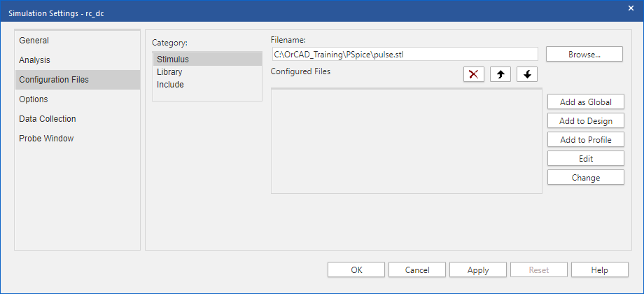
6. Left-click>OK to accept the Simulation settings
7. Left-click on the Run toolbar icon to run the simulation.
8. If you do not already have voltage markers on the IN and OUT nets, go back to the schematic and add them now.
Note
Instead of adding markers to the schematic, you can alternatively add traces (V(IN) and V(OUT)) in the Probe window using the Add Trace toolbar icon in the Probe window after the simulation has run.
9. View the results of the simulation in the Probe window.
10. Save the design file.
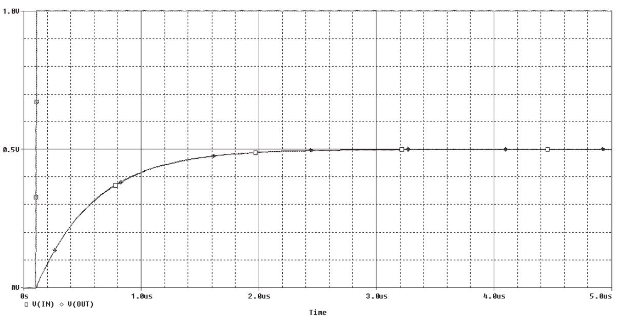
The waveforms illustrated in the next graphic shows how the voltage across the parallel resistor and the capacitor components ramps up to its steady state value.

End of Lab
All content Copyright 2022 Parallel Systems Ltd.