
All content Copyright 2022 Parallel Systems Ltd.
To complete the steps that follow, continue using the Buffer3 project you created in Lab 10-2.
1. From the Project Manager window select the File>New>Library menu commands to create a new library file.
The new library named .library<n>.olb, where <n> is a number, is listed within the Project Manager window as shown in the graphic that follows. (You may have more libraries listed)
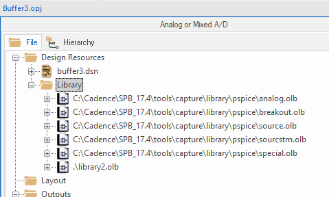
2. Left-click on the .library<n>.olb entry to select it and right-click>Save As
3. Name the library trng.olb and save it in the C:\OrCAD_Training\PSpice directory.
(Note: It is important to get into the habit of ensuring that the new library is saved into a known location with a known file name. Also, any user libraries should be stored outside of the OrCAD product installation directories)
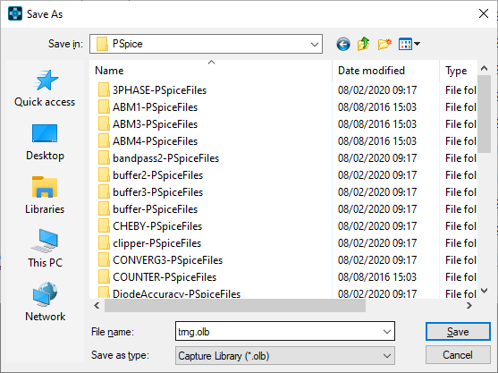
4. Left-click the trng.olb entry to select it and right-click>New Part
5. Name the new part LM324 and configure the properties as shown in the picture below.
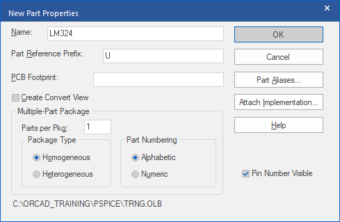
6. Left-click>Attach Implementation button and set the options from the following picture.
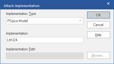
7. Left-click>OK to accept the settings and left-click>OK again to open the part editor.
8. Select Place>Line from the top menu, or the “place line” toolbar button, to draw the body of the part. The width and length of the part is about six grid spaces (not too critical)
Note that the dotted Bounding Box won’t be visible when the part is placed in the schematic so any visible lines will need to be drawn in the library part.
9. Select Place>Pin from the top menu, or left-click the “place pin” toolbar icon.
The Place Pin dialog box opens.
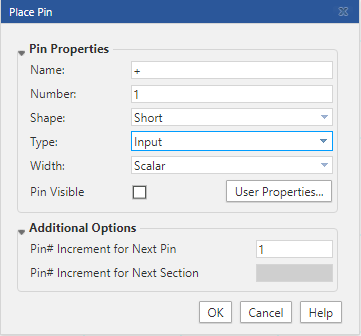
10. Define pin number 1 as an Input pin, as shown in the graphic that follows.
11. Place five pins around the body as shown in the next graphic.
• Define pin number 2 is an input pin, named –
• Define pin number 3 as an output pin named OUT
• Define pin number 4 as a power pin named V+
• Define pin number 5 as a power pin named V-
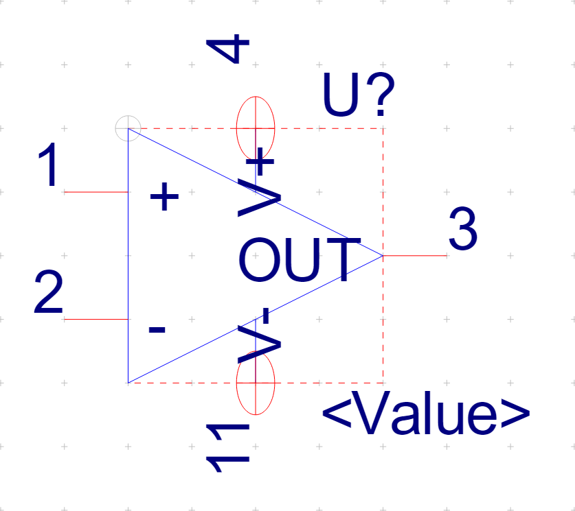
If necessary, you may edit a pin definition if you select the pin and modify the values in the Pin Properties on the right hand side.
12. Left-click on the V+ pin and set its Shape to Zero Length in the Pin Properties on the right hand side.
13. Also left-click the Pin Visible box to enable it.
14. Repeat steps 12 and 13 for the V- pin.
(Note, you might choose to keep the power pins short rather than zero length in your own parts)
15. If necessary, select each of the other pins and set their Shape to Short in the Pin Properties on the right hand side.
16. Draw additional lines to connect the power pins to the body of the part.
(If necessary, left-click the Grid Icon to turn off the “Snap to Grid” while drawing the lines to complete the part. Left-click the Grid Icon to restore the “Snap to Grip” once the part graphics have been completed)
17. Move to Part Properties on the right hand side and left-click on the “+” to add a new Property, select PSpiceTemplate from the drop-down.
(Move the mouse to the left hand side of the Properties Sheet and left-click and drag the edge to get some more typing space)
18. Type X^@REFDES %+ %- %V+ %V- %OUT @MODEL in the Value field.
Note that there are spaces before and after each of the pin references and parameters.

19. Left-click the “tick” to add the property
20. Select File>Save from the top menu to save the library file.
21. Start another New Project, name this project buffer4 and base it on the buffer project as before, then delete the LF411 in the circuit and replace it with the LM324 just designed.
22. Run the simulation (transient run to 5uS).
23. Examine the results in the Probe window.

End of Lab
All content Copyright 2022 Parallel Systems Ltd.