
All content Copyright 2022 Parallel Systems Ltd.
1. Create a new PSpice project called hier_clip based upon the empty project template.
2. Open the previous Clipper design and copy the circuit into the SCHEMATIC1 – PAGE1 of the hier_clip project.
(“Window select” the schematic items, close the previous Clipper design after making the copy of the schematic)
3. Edit the copy to resemble the circuit below.
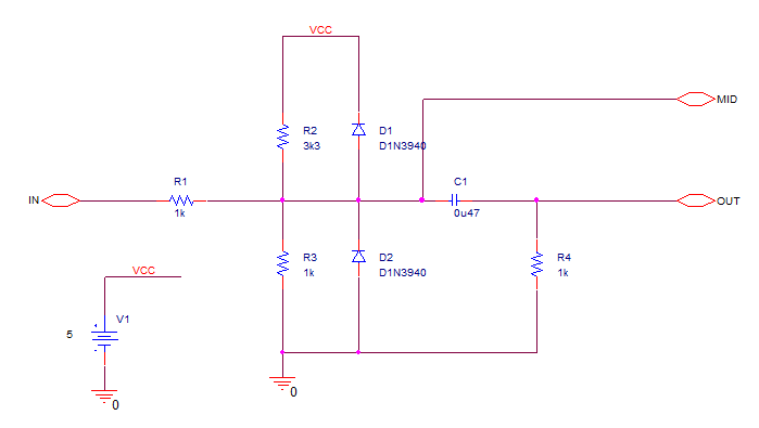
4. Save the file.
5. In the Project manager rename SCHEMATIC1 to Clip_bot by right-clicking on the name and selecting the Rename command.
6. Go to the Project Manager window.
7. Choose File>New>Library.
A new library called library<n>.olb is created. (<n> is a number)
8. Left-click the library<n>.olb just created to select it.
9. Right-click>Save As and name the file hier1.olb.
10. Right-click on hier1.olb and choose New Part from the pop up menu.
11. Type Clip_top in the Name field.
12. Left-click>Attach Implementation button.
13. From the Implementation Type field pull-down menu, choose Schematic View.
14. In the Implementation field type Clip_bot.
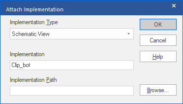
15. Left-click>OK twice.
The Part Editor opens and displays a dotted box with a reference designator and value.
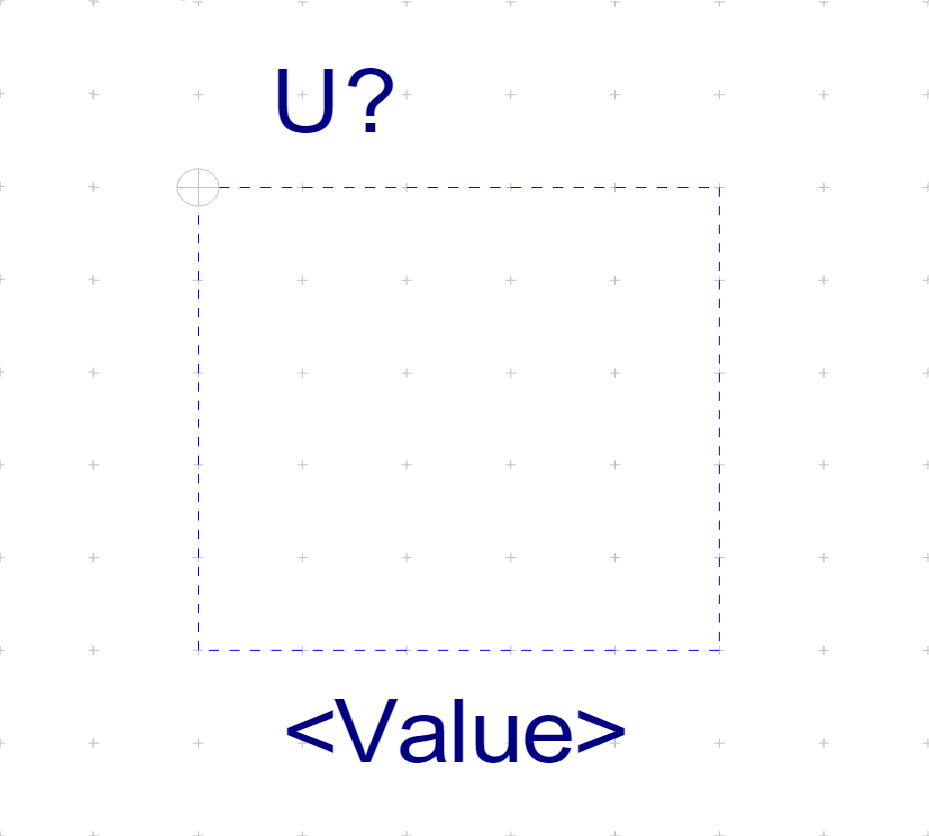
16. Use the Place>Rectangle command, or Place Rectangle toolbar icon, to draw a rectangle six grids high by several grids long.
17. Use Place>Pin from the menu, or Place Pin toolbar icon.
The Place Pin dialog box opens.
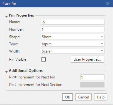
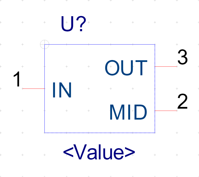
18. Define the pin properties of the first pin as shown in the above graphic.
19. Left-click>OK to attach the pin symbol to your cursor.
20. Left-click a location on the left edge of the rectangle to place the pin.
21. Place pins number 2, and 3 on the right edge of the rectangle.
22. Verify the pin names and numbers are assigned as shown in the graphic below.
23. Left-click on the <Value> property and move to the Basic Attribute section of the Property Sheet on the right hand side of the screen.
24. Left-click the  (Display Property) icon to the right of the Value edit box and select “Do Not Display” from the list.
25. Save the file and close the window.
26. In the Project Manager, add a new schematic folder called Clip_top to hier_clip.dsn by left-clicking the design name to select it, and then right-click>New Schematic
Or, you may select the design name in the Project Manager window, then choose the
Design>New Schematic menu commands.
27. Add a new page to the Clip_top schematic in the same manner.
28. Make Clip_top the root schematic by right-click>Make Root on the folder symbol next to the schematic name.
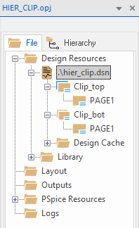
29. If prompted, Save the design to change the Root schematic folder
Reference Schematic:
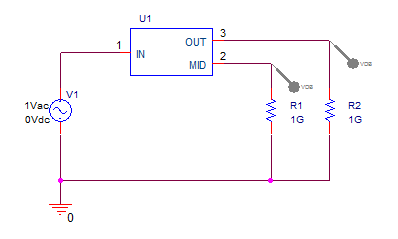
(Note: the screen shot above shows the completed schematic, it won’t be possible to add the “dB Voltage Markers” until after the simulation profile is configured in step 34.)
30. Go to Page1 of Clip_top
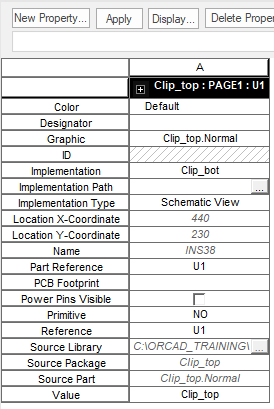
31. Place a copy of the Clip_top part on the schematic page and double-click the placed part to open the Property Editor.
Check that the Filter in the Property editor tab is set to <Current Properties>
32. Edit the properties of Clip_top and set Primitive to No.
33. Close the Property Editor window.
34. Draw the remainder of the schematic to look like the diagram above.
35. Create a new simulation profile running an AC Sweep in decades from 10Hz to 100MHz with 11 points per decade.
Note
As you enter values into the Simulation Settings, remember to enter Meg for MegaHz. Since “M or m” will represent milli, PSpice requires Meg.
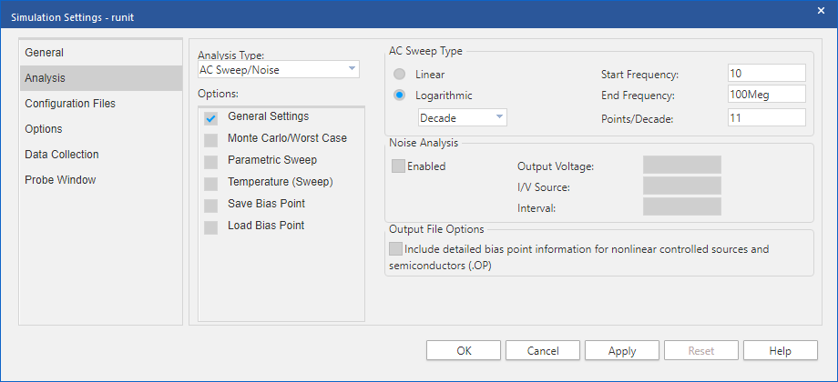
35. Run the simulation and examine the results in the Probe window. The results should match those from the earlier flat version of the clipper circuit.

End of Lab
All content Copyright 2022 Parallel Systems Ltd.