
All content Copyright 2022 Parallel Systems Ltd.
Reference Schematic:
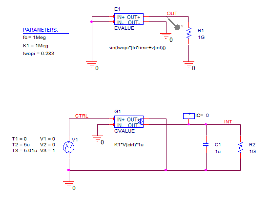
This circuit is a Voltage-controlled oscillator. The top portion of the circuit is a
simple time domain function for a sinusoidal source. It normally has the equation of
sin((twopi*fc*time)+phi), but here the constant phi has been replaced with a function of
a controlling source.
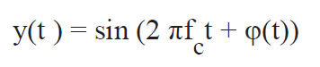
The instantaneous frequency is given by the time derivative of total phase:
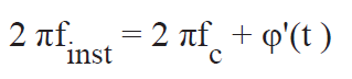
The relationship between f and the frequency deviation:
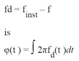
For a linear VCO we want fd to be proportional to the controlling voltage:
vctrl so
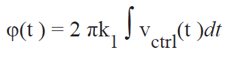
where k1 is in Hertz/volt.
1. Create a new project called VCO.opj based on the empty project template.
2. Enter the circuit shown at the top of this lab use: Evalue, Gvalue, IC1, R, C, Vpwl
and Param parts.
3. Set the value for the GValue to: K1*V(ctrl)*1u
4. Set the value for the EValue to: sin(twopi*(fc*time+V(int)))
5. Set the V1, V2, V3 and T1, T2, T3 properties for the Vpwl as shown in the
schematic. (V1=0, V2=0, V3=1, T1=0, T2=5u, T3=5.01u)
(Display the properties, as shown, if you wish)
6. Set the Parameters to be fc with a value of 1Meg. K1 with a value of 1Meg and
twopi with a value of 6.283.
7. Define a transient analysis simulation profile with the final time of 10us and a
maximum step of 10ns.
8. Run the simulation and examine the results.
You should see that the output of the VCO is 1 MHz for the first 5us and 2 MHz for the
next 5us.
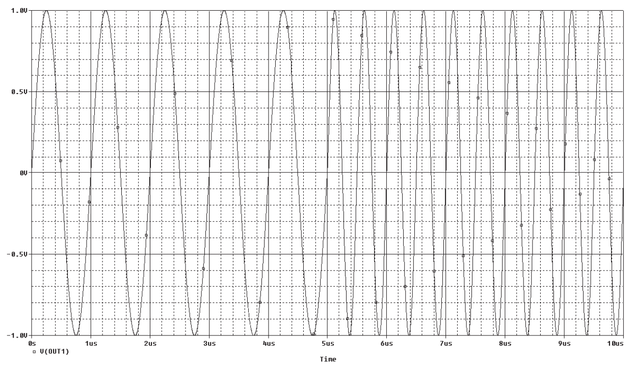
(In the formula, the rate of change of time is 1e-6 per microsecond, this results in the
base frequency of 1MHz, the carrier. After the pulse goes to 1V, the capacitor starts to
charge. It charges at a rate of 1V per microsecond, or 1e-6, this is added to the rate of
change of time and the resulting rate is 2e-6, and the frequency is doubled to 2MHz)
Q: What happens if you delete the “twopi” property from the PARAM part and re-run
the simulation?

End of Lab
All content Copyright 2022 Parallel Systems Ltd.