
All content Copyright 2022 Parallel Systems Ltd.
Reference Schematic:
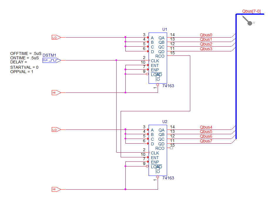
1. Left-click the Place Bus toolbar button, or use Place>Bus from the top menu, and draw a bus as seen in the schematic above.
2. Label the bus QBus[7-0].
(What would happen if the bus were named QBus[0-7]?)
3. Connect the Q outputs of U1 and U2 to the bus.
4. Use Place>Net Alias from the top menu to label the wires QBus0 through QBus7 from top to bottom in the same order as shown above.
Hint: You can use the auto-incrementing feature of the Net Alias function to speed up the process, QBus0 will become QBus1 on the cursor once QBus0 has been placed on a wire.
5. Place a voltage marker on the bus.
6. Rerun the simulation.
7. Zoom in so that you can see the values for the bus.
The default is HEX for bus values.
8. Left-click on the name of the bus for the trace
9. Choose Edit>Modify Object… or double-click on the name of the bus.
10. Change the Trace Expression to read {QBus[7:0]};;d
The bus values are now displayed in decimal format.

End of Lab
All content Copyright 2022 Parallel Systems Ltd.