
All content Copyright 2022 Parallel Systems Ltd.
Start PCB Editor from:
Start (Windows Icon) >Cadence PCB 17.4-2019>PCB Editor 17.4
The PCB Editor Canvas opens.
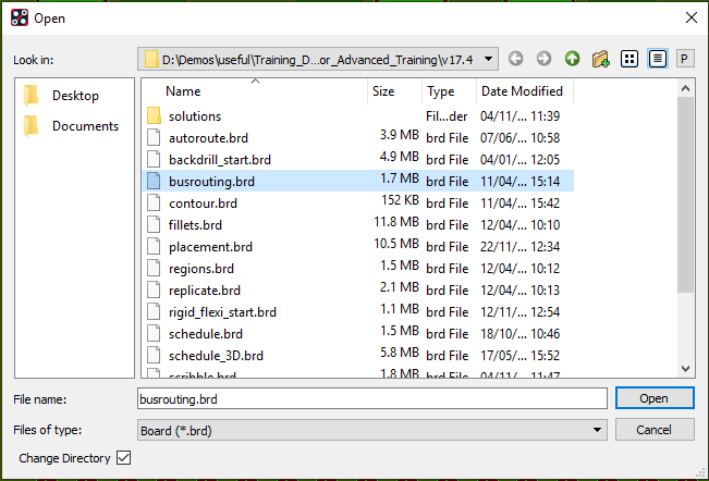
1. Select File>Open from the PCB Editor main menu.
2. If necessary, set the File Type for Board (*.brd)
3. Use the Browse button to navigate to the
C:\OrCAD_Training\PCB_Designer_Advanced directory, select the busrouting.brd file and left-click on Open
To assist with adding the Bus Routing some shortcuts have been defined. These are loaded from a script file, for this session but could be added to the env file to setup the shortcuts as PCB Editor starts.
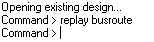
4. Load the shortcuts by running the script, left-click in the PCB Editor Command Window and type:
replay busroute
and press enter
For information, the shortcut definitions in the script file are:
# assign b to cycle through via patterns when a double-click is made
funckey b pop viapattern next pattern
# assign u to dynamically toggle the line to line space during group route to 0.254, 0.508, 0.762
funckey u ‘settoggle userspace 0.254, 0.508, 0.762; pop routespace user $userspace;echo routespace = $userspace’
# assign the space bar to add via(s)
funckey “ “ “pop bbdrill -cursor”
5. Set the Application Mode to Etch Edit:
Either
Setup>Application Mode>Etch Edit from the menu
Or
right-click>Application Mode>Etch Edit in the background canvas
Or
left-click>Etch Edit in the Application Mode section on the Status Bar
(This will probably be showing “General Edit”)
Or
use the Etch Edit Icon on the Application Mode Toolbar
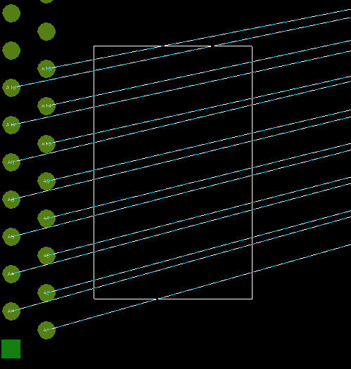
6. Drag a box around the rats coming out of the J2 connector, as shown
7. Hover over one of the selected rats and right-click>Add Connect
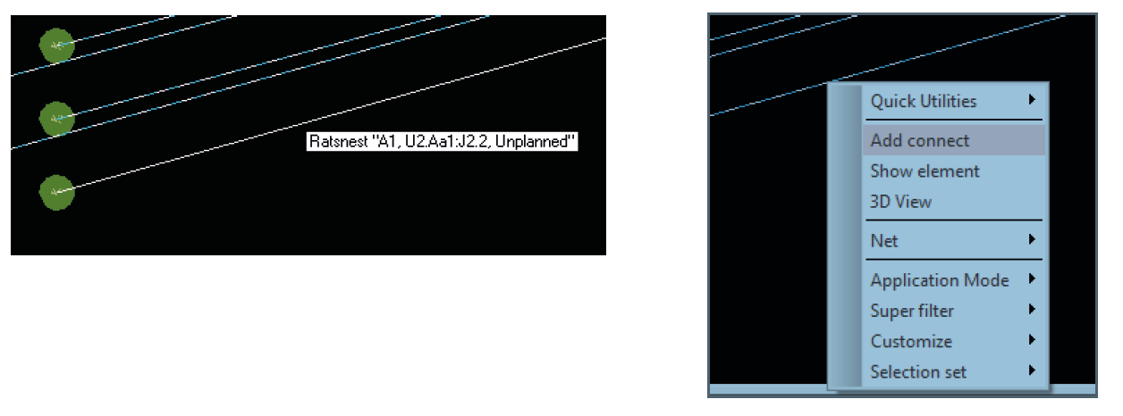
After the Group Routing starts, the control trace is the rat just hovered over before Add Connect above. A right-click>Change Control Trace will allow the control trace to be changed, use this and change the control trace to one at the middle of the group, J2.9.
The routes / rats will be blanked while the new control trace is selected, datatips will be shown for the pins to enable selection.
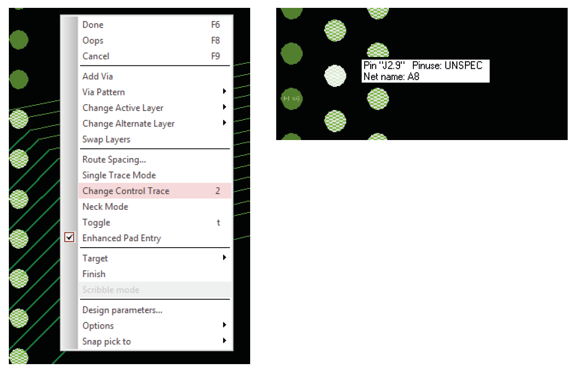
8. Once the routing is back on the cursor, right-click>Route Spacing to change the distance between the routes:
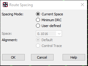
9. Left-click on OK to change the spacing to 0.381mm and then move the mouse to the right and left-click to add some traces.
10. Double-click to get a via pattern on the mouse cursor, this can be changed before placing.
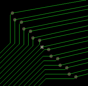
11. To change the Via Pattern, try switching between the choices using right-click>Via Pattern
12. Now select right-click>Via Pattern>Spacing and set the value as shown below in order to reduce the via spacing:
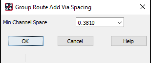
13. Place the vias using one of the selected patterns.
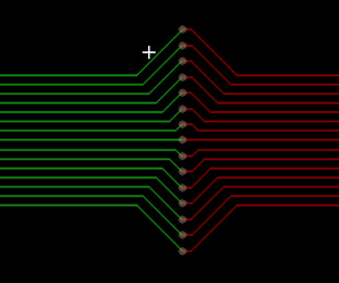
14. Take the Routing over to the BGA on the right. When close to the part try right-click>Single Trace Mode to complete the routing as single traces.
15. If time permits, experiment with different options when adding the Group Routing.
You could also try using the “b”, “u” and space bar shortcuts when Group Routing.
To the upper right of the board are some examples of the Via Patterns available.
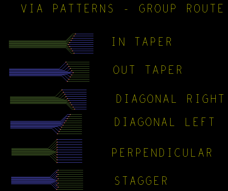

End of Lab
All content Copyright 2022 Parallel Systems Ltd.