
Today’s high-speed serial I/O technology handling 5 Gbps or higher presents new challenges for hardware engineers. Transitioning these high-frequency signals between layers can greatly affect signal integrity when a portion of plated through-hole (PTH) is left unused, forming a stub. By definition, these stubs are the unused section of the barrel where the signal is not required to travel.
This can be controlled in the design space by using the full length of the barrel for signal layer transitions thus keeping stubs to a minimum or with the use of blind or buried vias. If these options are not available, stubs can be removed through a board fabrication process called backdrilling, sometimes referred to as controlled depth counterboring.
Backdrilling is a board fabrication process that removes the unused section of plated through holes; typically connector pins and signal vias.
A secondary, controlled depth drilling pass(s) removes all electro-deposited plating material in the PTH ensuring signal stubs are minimized. Stubs are the source of impedance discontinuities and signal reflections which become more critical as data rates increase.
Backdrilling can be performed from either side of the PCB and to multiple depths. Drill sizes used for backdrilling are typically 0.1524mm to 0.254mm larger than the original tooling. Fabricators must be careful not to over drill beyond the calculated depths but also not to under drill, leaving unacceptable stubs.
Trade-offs between signal quality and manufacturing costs must be considered as well as the trade between signal integrity and board testability.
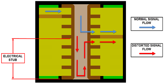
This lab introduces the Backdrill functionality. Backdrill data is stored in the library padstacks and utilized at the design level during the analysis and backdrill generation process.
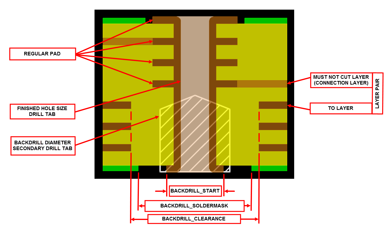
Padstacks which do not have pre-defined backdrill information can be automatically updated at the design level by entering the backdrill criteria prior to running backdrill. Design layers which are backdrilled will have Route Keepout Shapes generated to ensure design integrity is maintained with separate padstack definition controls for the backdrill start layer, internal layer and negative layer anti pad geometries without the need of custom padstacks or scripts.
All backdrill data is available on the individual Pin/Via objects displayed on the canvas or by simply querying the object using Show Element, and generating the Backdrill Legends and detailed Backdrill Report.
All content Copyright 2022 Parallel Systems Ltd.