
All content Copyright 2022 Parallel Systems Ltd.
OrCAD PCB Editor Professional has the ability to include both Pin delay and Z-Axis Delay when calculating differential pair phase and propagation delay checks. Electrons don’t just travel from pin to pin on single layers. They can travel in the z-axis through vias and pins as well as inside the package from die to pin. For high speed designs with delay rules, every piece (length) of copper needs to be included or you could be facing length mismatches which will cause performance issues. Before this feature this information would be added manually in Constraint Manager.
Now users can use a 2d field solver in combination with your stackup to calculate precise propagation and z axis length.
Start PCB Editor from:
Start (Windows Icon) >Cadence PCB 17.4-2019>PCB Editor 17.4
The PCB Editor Canvas opens.
1. Select File>Open from the PCB Editor main menu.
2. If necessary, set the File Type for Board (*.brd)
3. Use the Browse button to navigate to the C:\OrCAD_Training\PCB_Designer_Advanced directory, select the schedule_match.brd file and left-click on Open
4. Launch Constraint Manager>Electrical>Net>Routing>Relative Propagation Delay, select the bytelane0 matched group and right click>Analyze. Notice that the members all match within the required tolerance.
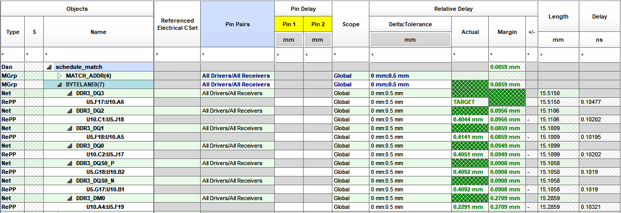
We will now simulate a pin delay change by the chip manufacturer to ensure we get the latest information from them. We will also enable the z-axis delay rules to include the via length in these calculations.
5. In PCB editor choose Import>More>Pin Delay and browse to the C:\OrCAD_Training\PCB_Designer_Advanced directory, change the files of type dropdown to All Files (*.*) and choose the BGA345_BD23X23MM.txt file. Select Open.
6. Left click U5 and left click Import. Close the form.
7. Go back to Constraint Manager>Electrical>Net>Routing>Relative Propagation Delay and notice the Pin delays have been added for U5.
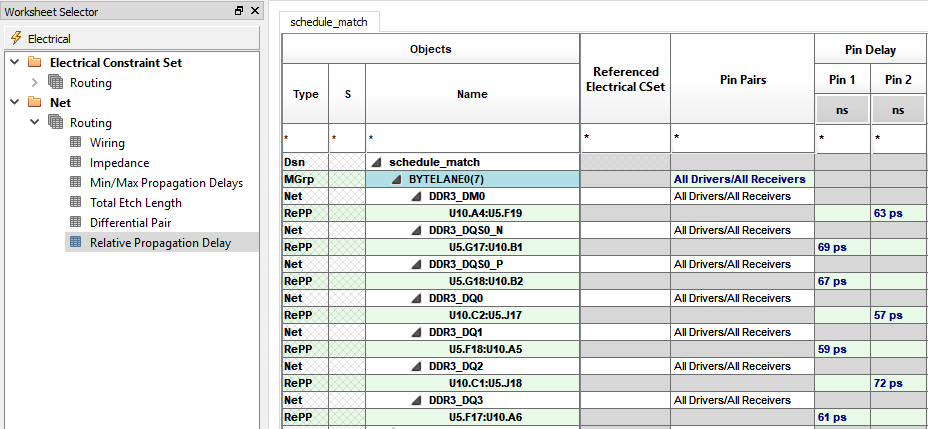
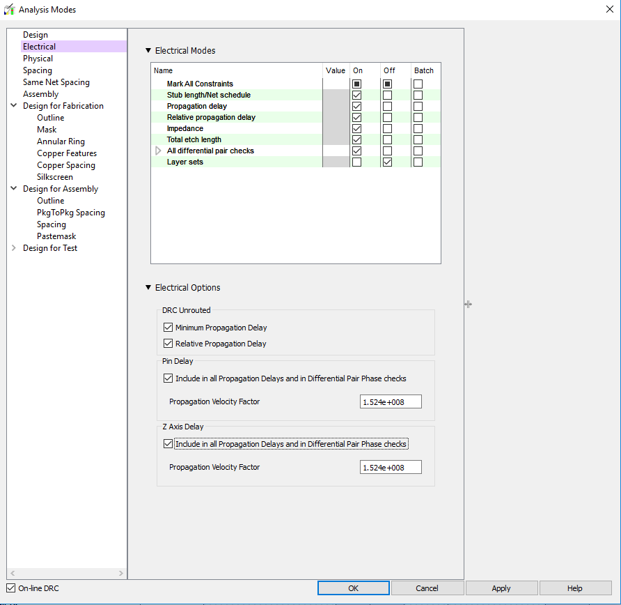
8. In Constraint Manager choose Analyze>Analysis Mode>Electrical and enable the checkboxes for Pin Delay and Z Axis Delay under Electrical Options. Click OK to close the form.
9. If required, re-select the bytelane0 match group and right click>Analyze. You should notice that some of the members of the bytelane0 now do not meet the requirements of the match group.
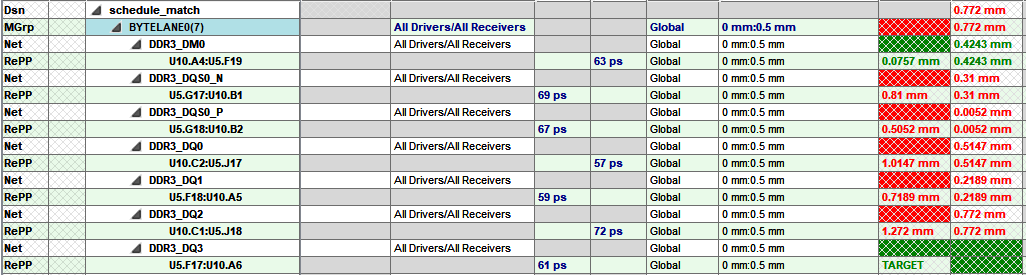
10. Go back to the main canvas and add or subtract length to resolve the DRC errors. The heads up display will indicate if you need to add or remove length. In some instances it is easier to remove the existing delay and re-add. You can use the delay tune command to remove tuning by invoking the command then start the delay at the start point and move across the existing delay and it will be removed.
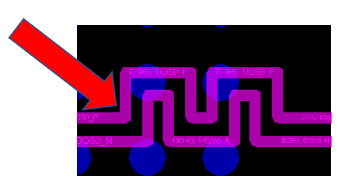
11. Save the board as schedule_pindelay.brd

End of Lab
All content Copyright 2022 Parallel Systems Ltd.