
All content Copyright 2022 Parallel Systems Ltd.
Dynamic Differential Pair Phase control allows you to ensure that the traces are running as close to each with respect to length, all the way from the start to the end. You can actively see DRC errors as you route to ensure you meet the length requirements.
Start PCB Editor from:
Start (Windows Icon) >Cadence PCB 17.4-2019>PCB Editor 17.4
The PCB Editor Canvas opens.
1. Select File>Open from the PCB Editor main menu.
2. If necessary, set the File Type for Board (*.brd)
3. Use the Browse button to navigate to the C:\OrCAD_Training\PCB_Designer_Advanced directory, select the schedule_phase.brd file and left-click on Open.
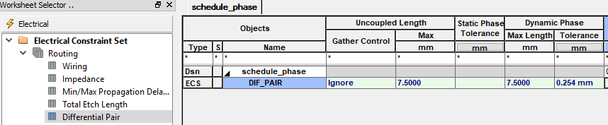
4. Open Constraint Manager>Electrical>Electrical Constraint Set>Routing>Differential Pair and add 7.5mm for Dynamic Phase max Length and 0.254mm for the Tolerance.
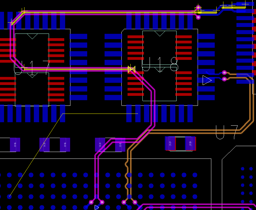
As the Phase routing already uses the ECSet above we can go straight to PCB Editor to see the result of this rule. (You may need to adjust your routing to look similar to below to see the “out of phase” DRC bars.
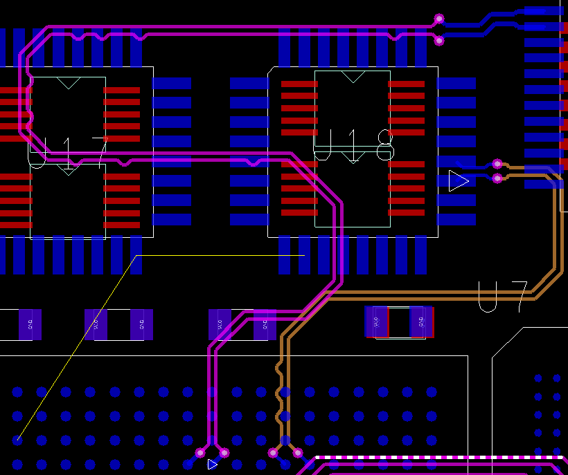
5. Using the Route>Phase Tune command with the Options set to 0.2mm for both Bump Length and Height see if you can resolve the DRC’s. the DRC phase bars show where the diff pair starts to go out of phase from Driver to Receiver. To help go to Setup>Design Parameters>Display tab and turn on the DiffPair driver pins option. Once complete it could look like:-
Save the board file as schedule_phase_dynamic.brd

End of Lab
All content Copyright 2022 Parallel Systems Ltd.