
All content Copyright 2022 Parallel Systems Ltd.
Start PCB Editor from:
Start (Windows Icon) >Cadence PCB 17.4-2019>PCB Editor 17.4
The PCB Editor Canvas opens.
1. Select File>Open from the PCB Editor main menu.
2. If necessary, set the File Type for Board (*.brd)
3. Use the Browse button to navigate to the C:\OrCAD_Training\PCB_Designer_Advanced\solutions directory (different from normal), select the rigid_flexi_routed.brd file and left-click on Open
4. We will first add some bend lines to this design so that we can show these in the 3D Canvas. Use Setup>Bends>Create.
5. For the start point of the bend hover over the inner radius of the first corner in the zone_1 and choose right click>Snap Pick To>Arc/Circle Center
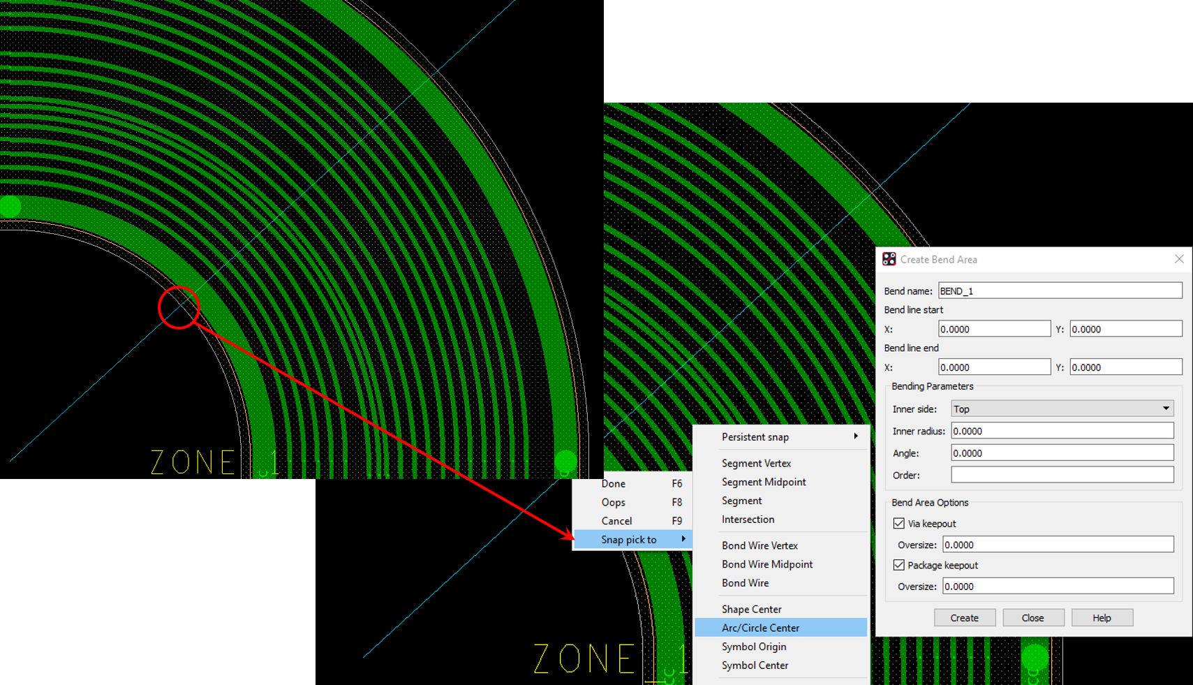
6. For the second part of the bend follow the line to the end then choose right click>Snap Pick To>Segment Vertex. You will notice that the values for the two pick points are now populated in the Create Bend Area form.
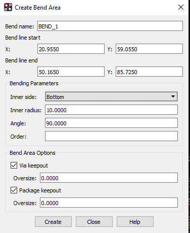
7. Set the rest of the values to match the figure below. If required add Via and Package Keepout oversize values to show the effect but in this instance they are not necessary then click on Create to add the bend, You will see the areas added.
8. Once bends have been added we need to define the static point for the 3D Canvas. This is the surface that will remain fixed when the view is bent, Use Setup>Anchor 3D View then choose any point within the top left hand part of the design with a left click (where the LCD is placed). Then choose right click>Done to end the command.
9. Launch the 3D Canvas using the icon or Display>3D Canvas.
10. Once the 3D Canvas is open right click in the canvas area and choose Bend then look to the Options pane of the 3D Canvas.
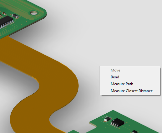
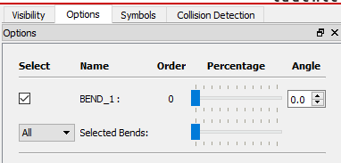
11. You can drag the bend “percentage bar” to the right to see the effect of the bend. if there are multiple bends the All bar will complete all bends in one step. The result should look similar to:
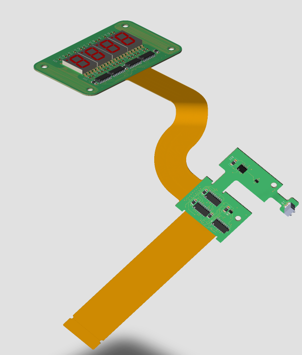
If you need to export a step model of the flexi in the bent state you can achieve this from the 3D Canvas command File>Export then set the Files of Type dropdown to STEP. You can also export a 2D and 3D PDF from this menu.
12. If required, close the 3D canvas and add additional bends on the other radius / flexi zones. If you need to adjust any you can use Setup>Bends>Edit then change the Bend name dropdown to match the bend you wish to edit.
13. There are additional DRC checks that can be run on Flexi Rigid designs. these will not be covered in this course but more information can be found on this subject by either looking at the Cadence documentation or there is a YouTube video here https://www.youtube.com/watch?v=71IwA_wAZtY
Manufacturing Data
14. PCB Fabricators require additional information when making a flexi rigid design so you will need to send them more data. Go to Manufacture>Cross Section Chart. Open the Table tab, set the units to millimeters (if required), set the Text Block size to 5 and enable the Zone Name under Table Column Options then click OK. Place the table on the canvas.
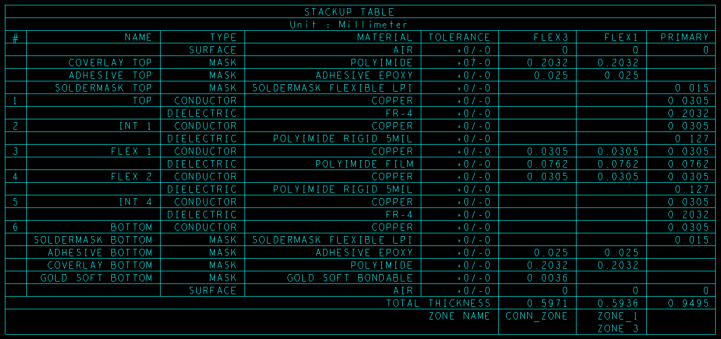
15. You can also create a cross section chart which would add all the charts in one step. You can then use Edit>Move, set the Find Pane to Groups and then separate the charts as required. Once separated, if the charts are updated the positions are remembered.
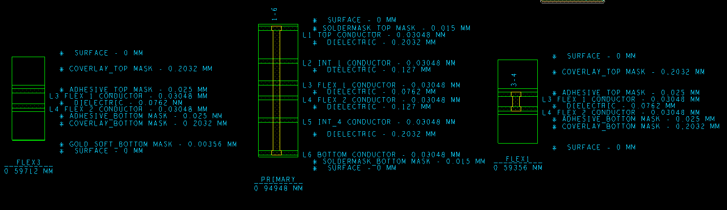
16. For the additional flexi and mask layers, Gerber films are added automatically since they are part of the Cross Section. Open Export>Gerber and click on Create Missing Films to add the soldermask films. For other mask layers you can create films as you would normally.
Data can be exported to a PCB Fabricator using Gerber, Excellon NC Drill files, ODB++ or IPC2581 which all support the additional flexi layers required.
17. Save the design as rigid_flexi_complete.brd.

End of Lab
All content Copyright 2022 Parallel Systems Ltd.