
All content Copyright 2022 Parallel Systems Ltd.
Start PCB Editor from:
Start (Windows Icon) >Cadence PCB 17.4-2019>PCB Editor 17.4
The PCB Editor Canvas opens.
1. Select File>Open from the PCB Editor main menu.
2. If necessary, set the File Type for Board (*.brd)
3. Use the Browse button to navigate to the C:\OrCAD_Training\PCB_Designer_Advanced directory, select the backdrill_start.brd file and left-click on Open.
4. Let’s refresh the design with the two library padstacks that had Backdrill data entered in the previous lab. (If you skipped this lab the padstacks are available in the solutions directory).
5. Using Tools>Padstack>Refresh, select Padstack list radio button and browse for the backdrill_pads.lst which contains the two padstack names that we need to refresh.

6. Select the Refresh button then select the View Log button to confirm the update was successful.
7. Select the Close button to close the Refresh Padstack dialog.
8. Padstacks s150h100 and c150h100 are used on connectors J2B1 and J2B2 (vertical connectors on the left) so to further verify the updates have been made review the padstacks that are currently loaded in the design. Zoom in to the Top Left corner of the design as shown below.
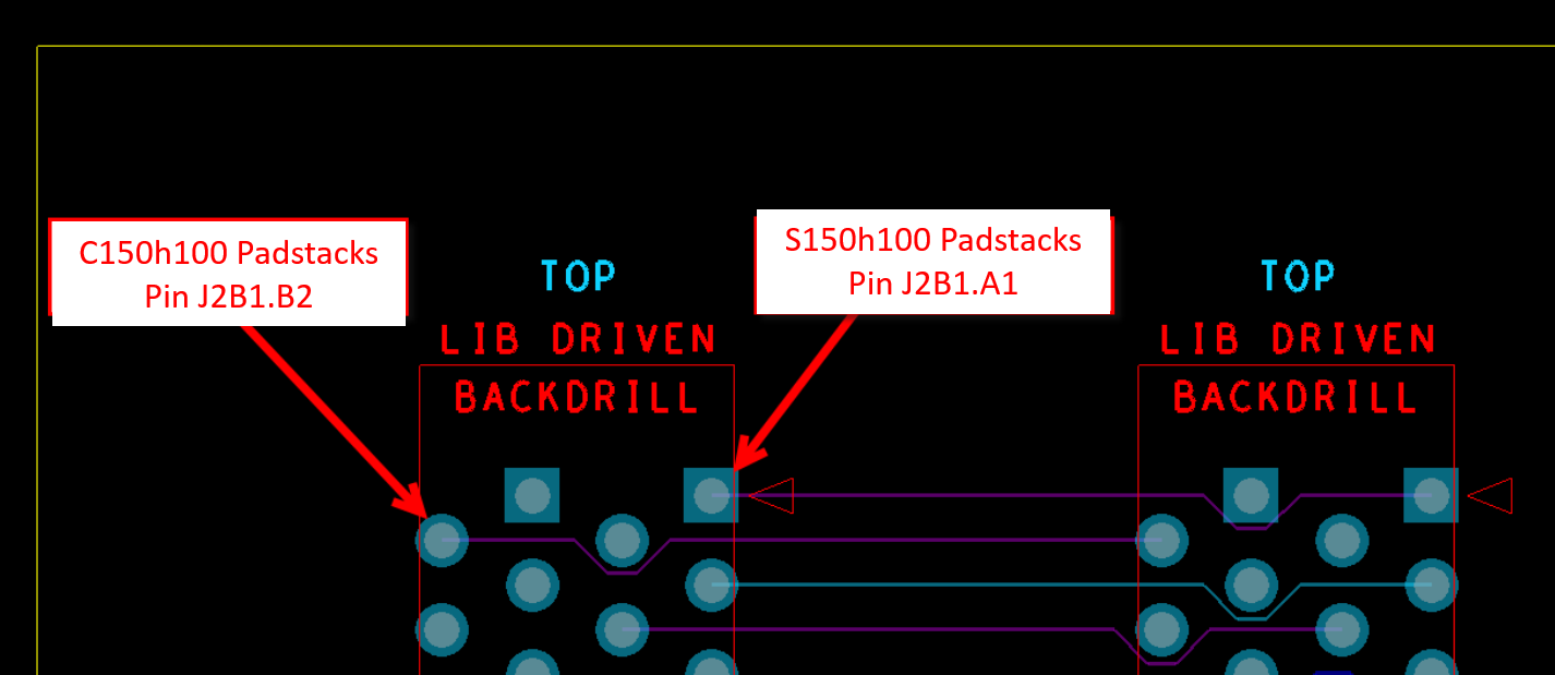
9. Hover over Pin J2B1.A1 and right click>Modify design padstack>All instances. The Design Padstack s150h100 will open in the Padstack Editor, review the Backdrill layers under the Design Layers and Mask Layers tabs.
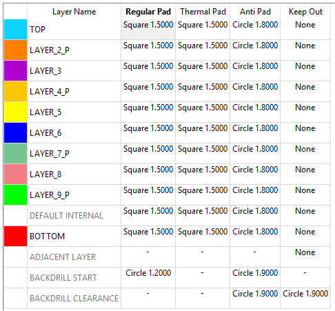
Once you have confirmed the padstack close Padstack Editor using File>Exit.
10. Go to Manufacture>Backdrill. If this is the first time Backdrill is being setup you will be presented with a Wizard-like dialog to assist in the creation of the Backdrill Layer Pairs.
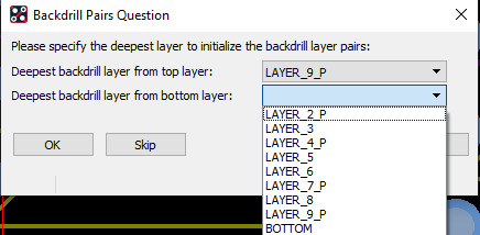
11. Select the deepest backdrill layers from each side of the board and select OK this will open the Backdrill Setup and Analysis form with pre-defined backdrill layers.
12. Right click>Delete Pair Set on the top Pair ID Row 1 for Start Layer TOP and repeat for Start layer BOTTOM (to clear the backdrills) then choose OK to exit the form..
13. Choose Manufacture>Backdrill again but this time select the Skip button to open the Backdrill Setup and Analysis form with no backdrill layers so we can create our own layer pair combinations.
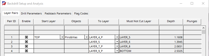
14. Right click>New Pair Set on the top row under the Layer Pairs tab to add your own custom layer pair backdrill. Set the Start Layer, Objects and To Layer cells as seen below and enter 3 as the Pair ID to add two additional layer pairs rows for the specified Start Layer.
15. Continue to specify backdrill stop layers (To Layer) and use right click>Insert Pair on any row to insert an additional Pair below the selected row on assigned Start Layer. Add the layers as shown below. Enable the pairs to include in the backdrill process.
16. If you Skip the Layer Pair setup wizard when Backdrill is first accessed or if you need to regenerate the backdrill layer pairs due to a design change you can run the Layer Pair setup again by selecting the Layer Pair Initialization button at the bottom of the form.
17. Backdrill Layer Pair Initialization dialog is separated into two sections:
Create layer pairs by the deepest backdrill layers (Initialization section): – Select the deepest layers for each side, enable check boxes on the right to generate layer pairs for Top / Bottom / Both then select the Create button in the section to create the backdrill layer pairs.
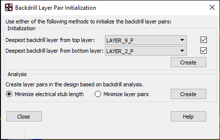
Create layer pairs based on Design Backdrill Analysis: (Analysis section): – Enable Minimize electrical stub length or Minimize layer pairs then select the Create button in the section to create the backdrill layer pairs based on the backdrill analysis of the design.
18. For this lab create layer pairs based on Design Backdrill Analysis based on minimized electrical stub length. Enable radio button for Minimize electrical stub length and select the Create button then select the Close button to review the Layer Pairs.
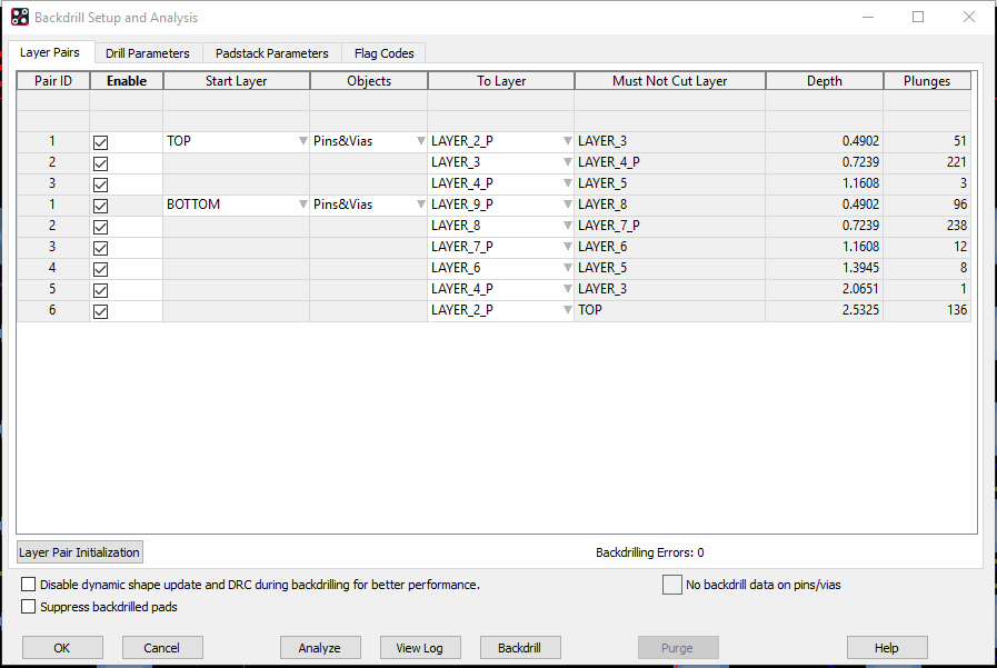
19. Analysis has already been completed during the Layer Pair Initialization step but to generate a detailed report select the Analyze button before committing any backdrill data to the database. (Depth calculations, backdrill candidates per layer pair, backdrill exclusions, etc.)
Note: One application for the analysis is to identify backdrill Layer Pairs which are underutilized to investigate, that after some minor routing changes which can eliminate the selected backdrill layer pairs and the reduce the cost of backdrilling.
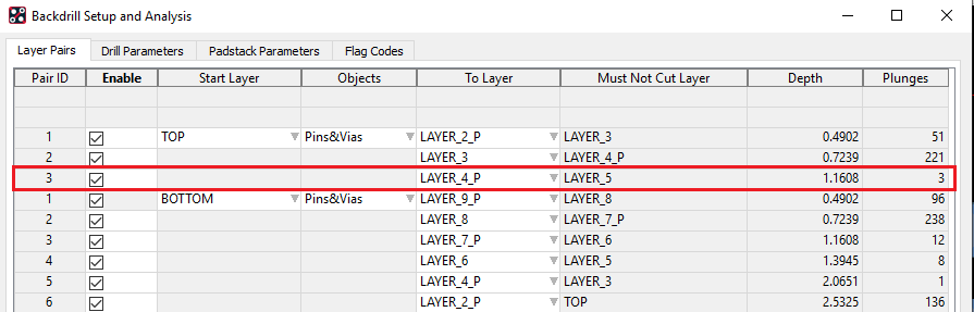
Note: After Analysis, the Layer Pairs tab will report the number of backdrill candidates (plunges) for each of the layers pairs and the report will detail type/location.
20. Scroll down to the Backdrill General Analysis section of the report
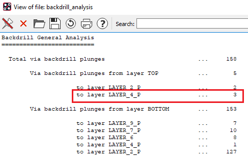
21. View the report in PCB Editor and click the X-Y Location to centre the display at the location of the proposed backdrill.
Note: Even after centring the display on the X-Y Location you still may need to zoom inward to clearly see the situation. (Report below has been edited to show the three nets in the same window).
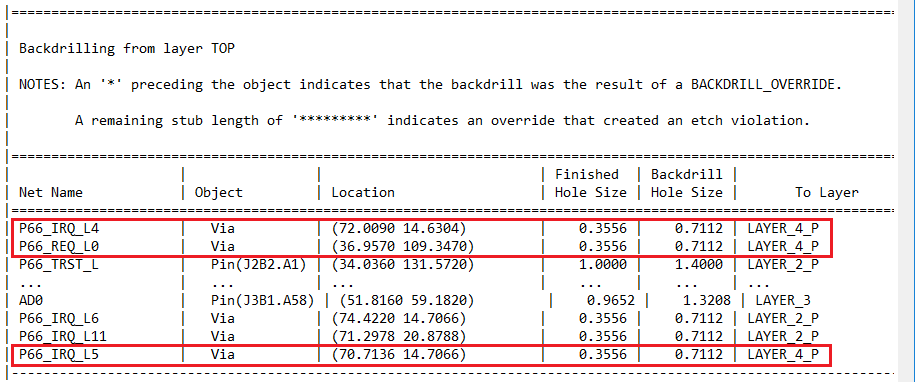
22. Review the horizontal trace connections (from LAYER_6, LAYER_8 and BOTTOM) and relocate them to LAYER_3 using hover on connect line (TAB key to cycle to the correct object type), right click>Change to Layer>Layer_3 to eliminate the need for the backdrill layer pair TOP to LAYER_4_P.
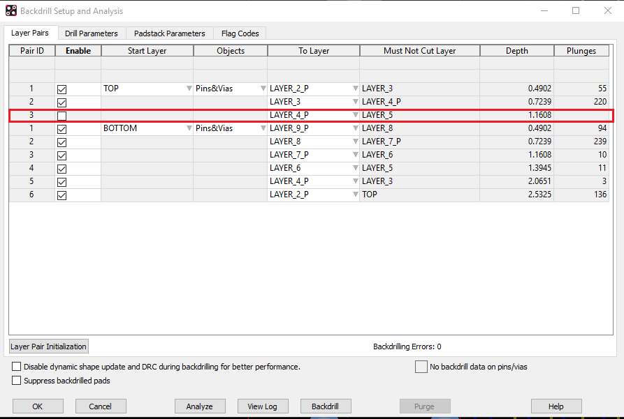
23. Select the Analyze button to see the results of making the minor routing changes. You can now disable TOP to LAYER_4_P as a Backdrill Layer Pair.
24. Select the Padstack Parameters Tab: Padstacks which do not have Backdrill data will be automatically updated based on the criteria in this tab. Padstacks with user defined Backdrill data, from the Library or manually entered in the design padstacks, will be used during the Backdrill process and will not be updated based on this criteria.
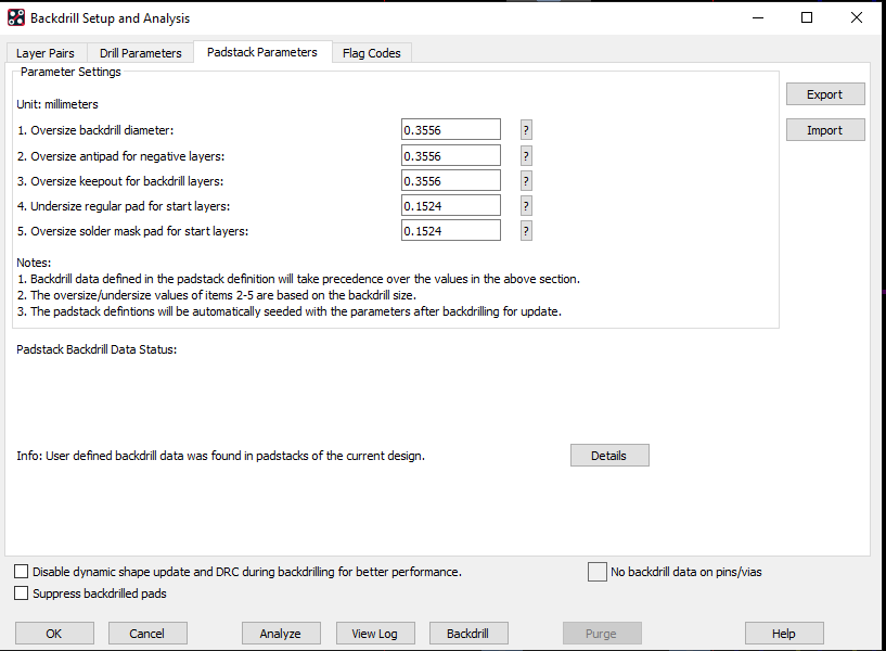
25. Select the Details button to list all padstacks in the design and identify the padstacks which have user defined backdrill data.
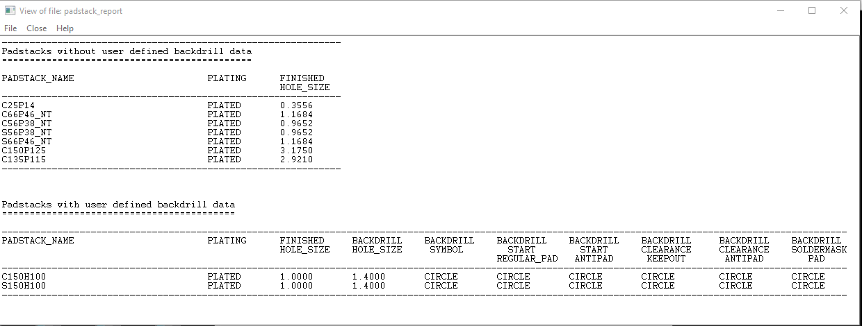
26. Adjust some of the values under the Padstack Parameters Tab and re-run backdrill again to see the different results in the updated padstacks.
Note: Only padstacks which do not have any backdrill data will be updated using the Padstack Parameters, all other padstacks with user defined backdrill data entered in the design or in the library will remain unchanged.
Note: It is recommended to enter the backdrill data in the library padstacks to ensure a consistent result when backdrill is executed.
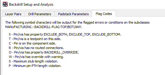
27. Running Analysis also generates special Flag Codes to assist in troubleshooting backdrill failures.
Figures are generated on MANUFACTURING BACKDRILL-FLAG-TOP, BACKDRILL-FLAG-BOT and BACKDRILL-FLAG-ANY subclasses which are identified under the Flag Codes Tab of the Backdrill Setup and Analysis form.
28. Select the Backdrill button to analyze and generate backdrill data for the pins/vias in the design that require backdrilling.
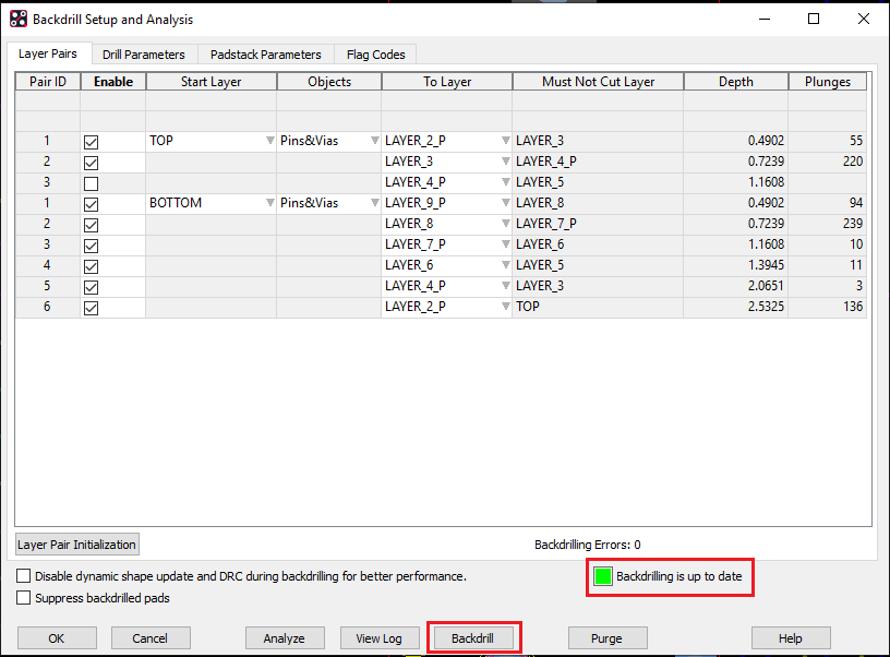
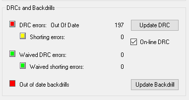
29. Performing design changes, like moving a component or sliding a Via that contain backdrill data will immediately remove all backdrill data from the object. Backdrill status will report that it is out of date with a Red status.
30. The status form (Check>Design Status) now includes Backdrill status for quick reference and an Update Backdrill button to open the Backdrill Setup and Analysis form so Backdrill can be updated.
31. Save the design as backdrill_complete.brd and move onto the next topic.

End of Lab
All content Copyright 2022 Parallel Systems Ltd.