
All content Copyright 2022 Parallel Systems Ltd.
Start PCB Editor from:
Start (Windows Icon) >Cadence PCB 17.4-2019>PCB Editor 17.4
The PCB Editor Canvas opens.
1. Select File>Open from the PCB Editor main menu.
2. If necessary, set the File Type for Board (*.brd)
3. Use the Browse button to navigate to the C:\OrCAD_Training\PCB_Designer_Advanced directory, select the backdrill_complete.brd file and left-click on Open.
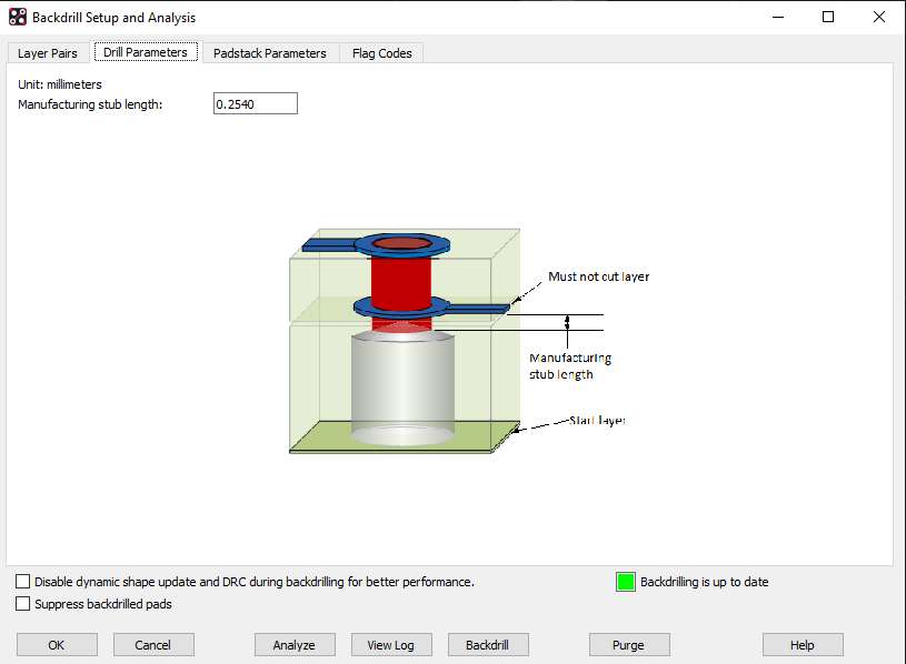
This lab will cover the advanced setup in specifying the manufacturing stub length to verify the remaining stub length after backdrill is manufacturable. This is a Fabrication vendor driven value and should not be confused with the minimum Electrical Stub requirements defined using the BACKDRILL_MAX_PTH_STUB Property.
4. Start with Manufacture>Backdrill.
5. Select the Drill Parameters Tab and enter 0.254 for the manufacturing stub length.
6. Open the Layer Pairs Tab and you will see a Yellow Cell under the depth column where the total thickness of the “To Layer” + “Dielectric” is less than the entered stub value.
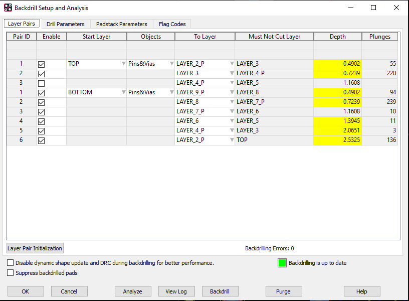
7. The layer pair rows for TOP to LAYER_4_P and BOTTOM to LAYER_7_P is not being reported as an issue because the minimum stub length after backdrill can be achieved, for example:
- “To Layer (0.03048mm)” + “Dielectric (0.4064mm)” = “0.43688mm”
- Total Thickness is 0.43688mm which is greater than 0.254mm stub length.
8. Selecting the Yellow Cell on the layer pair row for BOTTOM to LAYER_4 and review the result dialog:
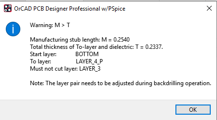
Note: The fabrication vendor will need to adjust the To Layer to meet their minimum stub length after backdrill which would result in them moving it to LAYER_5 with the stub spanning two layers. All Backdrill data will still be generated, even when these Warnings exist.
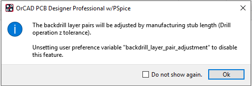
9. Backdrill Analysis can take into consideration the specified Manufacturing Stub Length and make adjustments during layer pair creation by setting a special environmental variable.
- Select the OK button to close the Backdrill Setup and Analysis form.
- Open User Preference Editor (Setup>User Preferences)
- In the Manufacture>Drilling category enable the variable “BACKDRILL_LAYER_PAIR_ADJUSTMENT”
- Select the OK button to close the User Preferences Editor.
- Open Backdrill Setup and Analysis (Manufacture>Backdrill)
- Select the Layer Pair Initialization button under the Layer Pairs Tab
- Under the Analysis section enable Minimize electrical stub length then select the Create button in the section to re-create the backdrill layer pairs.
- Select the Close button to return back to the Layer Pairs Tab to review the created Layer Pairs.
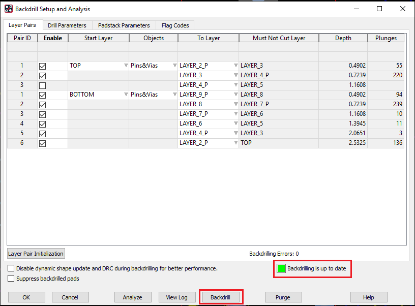
- You will see the Layer Pairs (To Layer and Must Not Cut Layer) have been shifted to support the Manufacturing Stub Length.
From:
To:
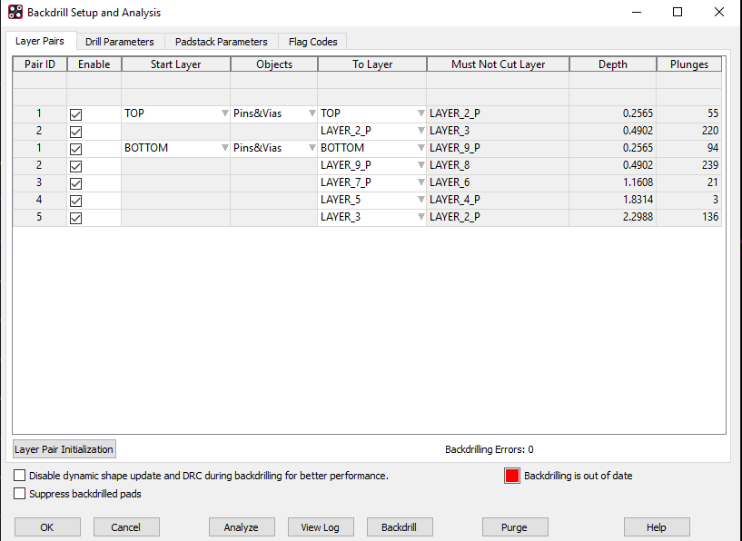
Note: The layer pair shift resulted in a couple Bottom side backdrill layer pairs to be combined with all others shifting up or down one layer depending on the backdrill side.

10. Once the layers pairs are regenerate Backdrill will be out of date. Select the Backdrill button to analyze and generate backdrill data for the pins/vias based on the new layer pairs.
With the “BACKDRILL_LAYER_PAIR_ADJUSTMENT” environmental variable set you will see this following message, select the OK button to continue.
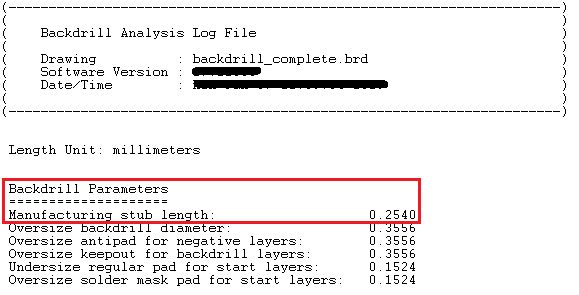
11. Select the View Log button to view the Backdrill Analysis Log File. It will now report a Remaining Stub Length for backdrill locations which had the layer pair shift away from the connection layer.

- Remaining Stub Len column is the distance from the shifted Must Not Cut Layer to the actual connection layer. (“To Layer” + “Dielectric” thickness)
- Maximum PTH Stub column is the Electrical Stub defined on the net using the BACKDRILL_MAX_PTH_STUB Property.
- Manufacturing Stub Length is reported in the Backdrill Parameters section in the header of the Backdrill Analysis Log File and in Backdrill Drill Legends.
12. Do NOT save the design. We will use the original design in the next lab.

End of Lab
All content Copyright 2022 Parallel Systems Ltd.