
All content Copyright 2022 Parallel Systems Ltd.
Start PCB Editor from:
Start (Windows Icon) >Cadence PCB 17.4-2019>PCB Editor 17.4
The PCB Editor Canvas opens.
1. Select File>Open from the PCB Editor main menu.
2. If necessary, set the File Type for Board (*.brd)
3. Use the Browse button to navigate to the C:\OrCAD_Training\PCB_Designer_Advanced directory, select the backdrill_complete.brd file and left-click on Open.
4. You have the ability to include the backdrill data as part of the NC Drill legend chart. To do this go to Manufacture>Create Drill Table, then enable the option for include backdrill.
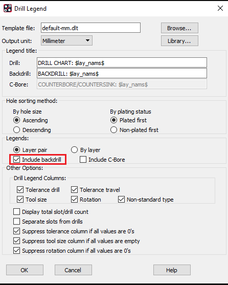
5. Select the OK button to generate Backdrill Legends which now includes detailed backdrill information and not just the Finished Hole Size requiring backdrill operation.
Note: If this is the first time you have generated the drill charts all charts will be placed on top of one another. Use the Edit>Move command with Groups enabled in the Find pane to separate and place them.
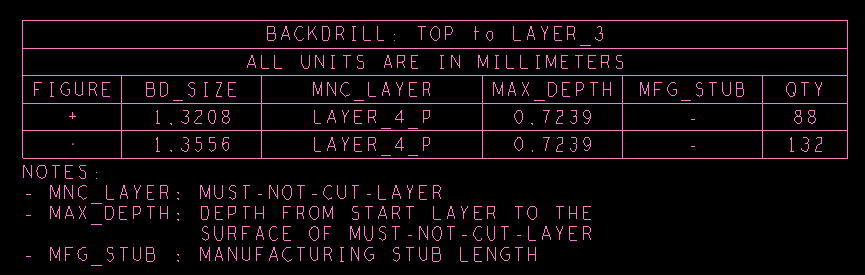
Actual NC drill data is exported using the Export>NC Drill or Export>IPC2581 or Export>ODB++ as you would any for any PCB fabrication data..
6. We can also generate a cross section chart which will show the backdrill operations in the design stackup. To do this use Manufacture>Cross Section Chart, then enable the option for backdrill span.
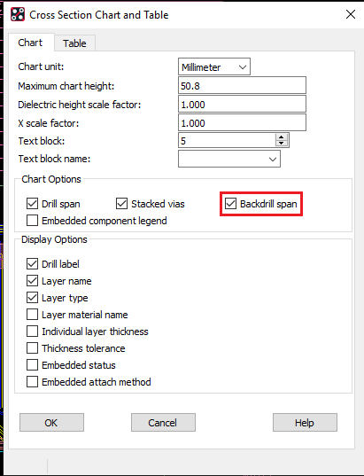
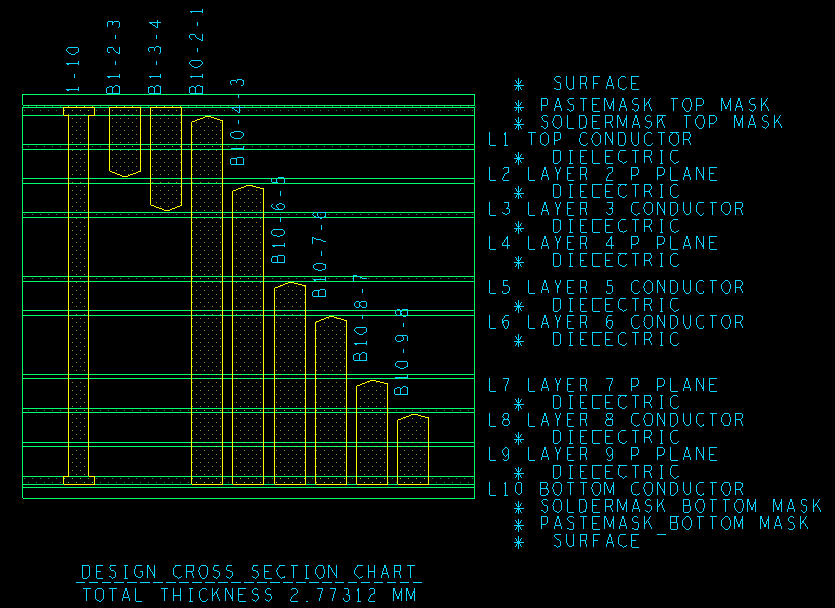
7. Select the OK button to generate a Cross Section Detail. You will see a tapered at the end of Backdrill Span along with the Backdrill Label seen on the canvas.

End of Lab
All content Copyright 2022 Parallel Systems Ltd.