
All content Copyright 2022 Parallel Systems Ltd.
If you worked through Labs 7-1 to 7-3 to use the Constraint Manager in PCB Editor, skip these labs, 7-1a to 7-3a
1. Close PCB Editor, if it is still running, save the unplaced.brd if prompted to save.
2. Start OrCAD Capture again and select an OrCAD PCB Designer Standard, or Professional, or OrCAD PCB Designer Standard, or Professional, with Capture CIS option license if you see the License Picker and open the Release project.
3. Select the Release.dsn file entry in the Project Manager window
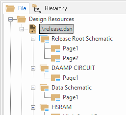
4. Start the Capture Constraint Manager, Tools>Constraint Manager, or left-click the CM icon
5. The “Enable Constraint Manager” form appears.
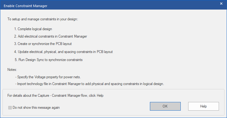
6. Left-click>OK
The “Migrate Constraints” form appears.
7. Select the “Migrate Constraints from PCB Layout” option
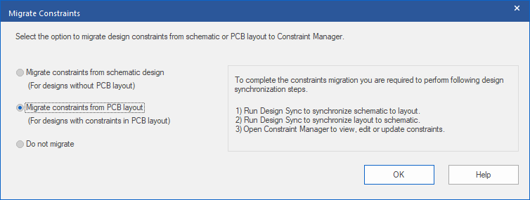
8. Left-click>OK
The “Assign Voltage to Power Nets” form appears
Accept the defaults, or set Voltages as required
9. Left-Click>OK
Now the migration sequence needs to be completed.
10. Use PCB>Update Layout from the main menu
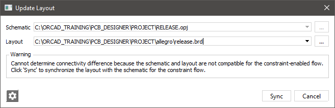
11. Left-click>Sync to update the board.
(This will update the Release.brd file created from Capture in the Initial Board Creation lab)
12. Close the Constraint Difference Report window and pick an OrCAD PCB Designer Standard, or Professional, license to start PCB Editor.
13. Back in the Capture window, start PCB>Update Schematic
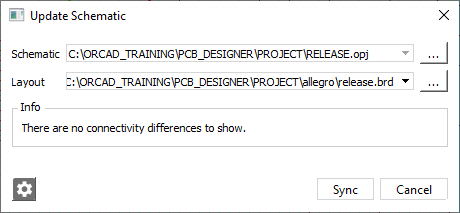
14. Left-click>Sync
15. Close the Constraint Differences Report window.
16. Use File>Save to save the Capture design
Now the schematic is ready to edit the Constraints
17. Start the Capture Constraint Manager, PCB>Constraint Manager, or left-click the CM icon
18. Left-click>OK on the “Enable Constraint Manager” form
19. Left-click on the Physical Domain at the left-hand side
20. Select the All Layers Worksheet under the Physical Constraint Set folder.
21. In the Default row, left-click in the Min Line Width and Min Neck Width cells and change the values to 0.15, as in the following graphic:

(Take care to select the individual cells and not the entire row when editing)
22. Left-click the Default cell to select the entire row.
23. Select Objects>Create>Physical CSet from the Constraint Manager menu (Or right-click>Create>Physical CSet in the Default cell)
24. In the Create Physical CSet form, type Clocks and left-click>OK
25. In the Clocks row, left-click in the Min Line Width and Min Neck Width cells and change the values to 0.2 as in the following screen shot:
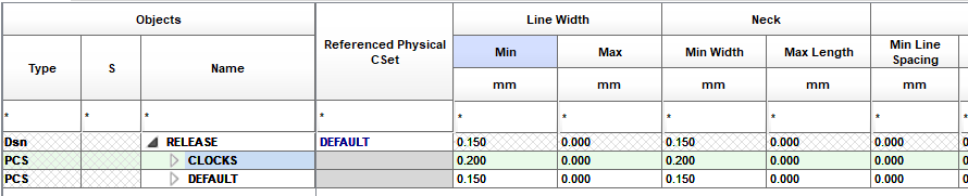
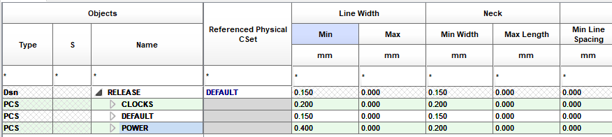
26. Left-click the Clocks cell and right-click>Create>Physical CSet.
27. Name the new Physical CSet Power
28. In the POWER row, left-click in the Min Line Width cell, change the value to 0.4
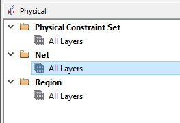
29. Select the All Layers worksheet under the Net folder as shown below.
30. Scroll down through the list of nets section so that both the VCLKA and VCLKC nets are visible.
31. Left-click to select the VCLKA net, and shift+left-click the VCLKC net so that both nets are selected, or drag-select the two net names.
32. Right-click>Create>Class from the pop-up menu.
33. Enter the name SYNC in the Net Class field. Verify that the “Create for both physical and spacing” option is checked, and left-click>OK.
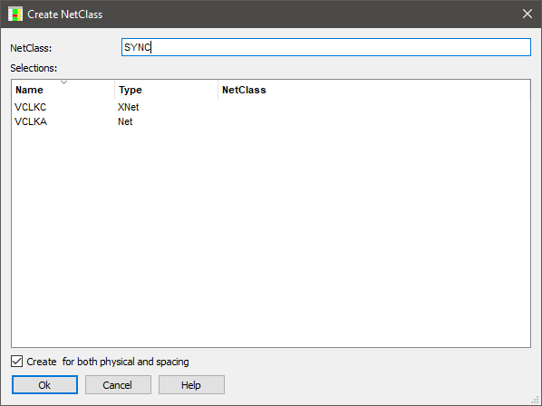
34. Scroll back to the top of the list of Nets and see that the SYNC class has been created with two members, VCLKA and VCLKC, select the Referenced Physical CSet cell in the SYNC row and select Clocks from the pull-down menu as shown.
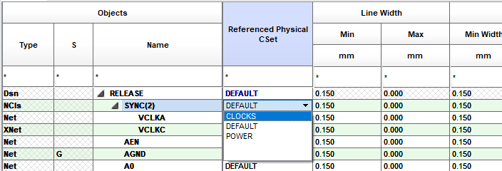
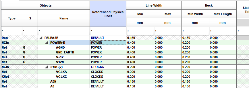
The NET_PHYSICAL_TYPE and NET_SPACING_TYPE properties that were added to the schematic in the previous session lab will have been retained as Classes since Update Layout was used to enable the Constraint Manager flow.
35. Select the POWER Class and select Power as the Referenced CSet.
36. Move to the Main Capture window and use File>Save to save the DSN file at this stage.
37. Left-click>Yes All if prompted by the “save” message
End of Lab
All content Copyright 2022 Parallel Systems Ltd.