
All content Copyright 2022 Parallel Systems Ltd.
1. From the top menu, choose Place>Components Manually.
The Placement browser window appears.
2. If necessary, select the Components by refdes drop-down menu option from the Placement List folder tab.
3. Scroll through the list and enable the check box to the left of U5.
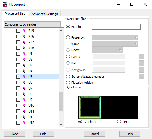
An outline view of the footprint is displayed in the Quickview window, and the Editor message area states:
Placing U5 / EPF8282A/LCC_PLCC127P3022X3022X / PLCC127P3022X3022X457-84N on Top.
4. Move the cursor into the main PCB Editor window. If necessary, move the Placement browser window to see the board location.
U5 is attached to the cursor. Before placing U5, it needs to be rotated.
5. Right-click>Rotate from the pop-up menu.
A “handlebar” extends between the part and the cursor.
6. Use the handlebar to spin the component.
Notice the angle reading in the Status area to the right of the “P” “A” buttons.
7. Rotate U5 to 270 degrees.
(Once anti-clockwise, or three times clockwise with the default 90 degree increment)
8. When the Status area shows that U5 is in a +270-degree rotation, left-click to accept the current orientation.
The part is no longer in the rotate (spin) command but it still attached to the cursor for moving.
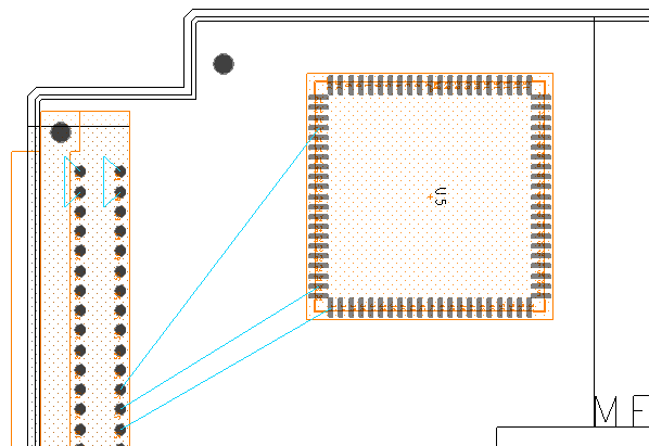
9. Left-click to place U5 in the design at the location shown in the figure.
10. Right-click>Done from the pop-up menu.
11. Select Setup>Colors in the top menu.
12. In the Color Dialog form select the Nets tab at the top of the form.
13. Left-click on a colour tile in the colour palette, say a green colour that you haven’t previously used in your colour setup.
14. In the Nets tab scroll down to the GND net and left-click on the Net colour box next to GND.
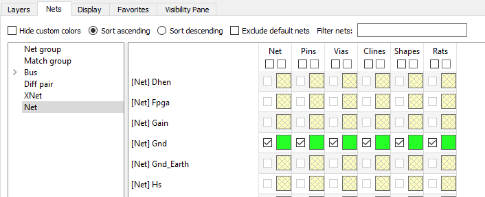
(The left hand column cells are “enable visibility” and the right-hand column cells are “assign colour”)
15. Left-click on another colour tile from the colour palette, say purple this time to use to colour the next net.
16. In the Nets display window scroll down to the VCC net and left-click on the Net colour box next to VCC.
17. Left-click>OK to close the Colour dialog.
This will colour all the pins that are assigned the VCC net in the selected purple colour.
18. Select Setup>Design Parameters from the top menu.
19. Left-click the Design tab to bring it forward.
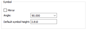
20. Set the Angle field to 90, as shown:
21. Left-click>OK to exit from the Design Parameter Editor form.
Now the default orientation is 90 degrees (instead of zero).
22. Choose Place>Components Manually from the top menu.
The Placement form appears.
23. Select the Components by refdes pull-down menu option.
24. Scroll through the list and enable the check box to the left of U1.
U1 appears in the Quickview window.
25. Move the cursor into the PCB Editor window.
U1 attaches to the cursor in a 90-degree rotation. The dynamic ratsnest lines appear between the component on your cursor and any currently placed components.
26. Left-click to place the U1 component on the board at the location indicated in the next figure.
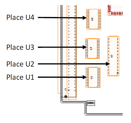 (“rats” not shown for clarity)
27. Place components U3, U4, and U2 using the method you just tried. Refer to the above figure for where to place the components.
28. Right-click>Done from the pop-up menu to complete the command.
29. Choose Place>Components Manually from the main menu.
30. Select the Hide button to close the form but remain in the current command.
31. Left-click and select a part to move, left-click to place it in a new location.
32. Practice this Move command with other parts.
33. Right-click>Done from the pop-up menu.
34. Finally, move a group, select Edit>Move from the top menu.
35. In the Find Filter, toggle everything OFF except Symbols.
36. Left-click and drag the mouse to draw a frame around the group of components to move.
37. When the parts to move are highlighted, left-click (but do not hold) to define an origin, or reference point, for the group to move. The group is then attached to the cursor.
38. Move the group around and left-click on a new grid location to place the group.
39. Right-click>Done from the pop-up menu.
40. Save the board as partplaced.brd.
End of Lab
All content Copyright 2022 Parallel Systems Ltd.