
All content Copyright 2022 Parallel Systems Ltd.
1. Start OrCAD Capture or OrCAD Capture CIS refer to Lab 6-1 for details, if required.
2. If the Cadence Product Choices form appears, select an OrCAD PCB Designer license and left-click>OK.
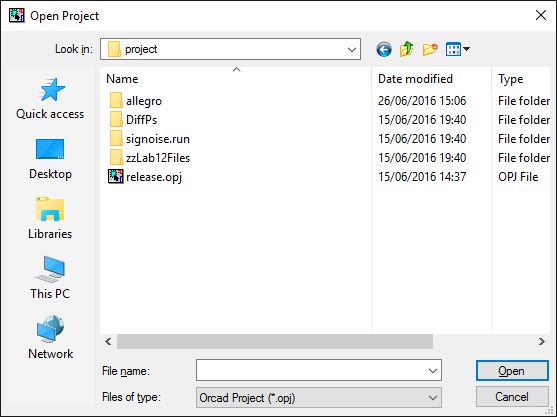
3. Select File>Open>Project.
A file browser window opens.
4. Navigate to the C:\OrCAD_Training\PCB_Designer\project working directory, select release.opj, and left-click>Open.
5. Select Options>Preferences.
6. In the Miscellaneous tab, check / set Enable Intertool Communication option and then left-click>OK.
7. Left-click the + symbol on the left side of release.dsn to expand the design.
8. Left-click the + symbol on the left side of Release Root Schematic to expand the drawings in the design.
9. Double-click Page1 of the Root Schematic to open that drawing.
10. Start PCB Editor and open the unplaced.brd file in the project\allegro directory, if it is not the active design.
11. Arrange OrCAD Capture or OrCAD Capture CIS and PCB Editor so that they each occupy half of the screen, or one on each screen if two monitors are available.
12. In PCB Editor, select Display>Zoom>Fit to see all of the PCB Editor board.
13. In PCB Editor, select Place>Components Manually.
14. Left-click>Hide in the Place Manually form.
15. Move the mouse into the OrCAD Capture or CIS Page 1 schematic window and select one of the FCT components (U1, U3 or U4)
16. After selecting the component in the schematic, move the mouse back to PCB Editor and the component will be attached to the cursor.
17. Practise cross selecting components in OrCAD Capture or OrCAD Capture CIS and moving them in Editor. When you have finished, right-click>Done from the pop-up menu in PCB Editor.
18. In PCB Editor, select Display>Highlight from the menu.
19. Left-click on a part in PCB Editor.
The corresponding component in OrCAD Capture or CIS is selected.
20. Left-click on several more parts in PCB Editor.
The corresponding components in OrCAD Capture or CIS are selected. The selection in OrCAD Capture or CIS is cumulative. If a different schematic page contains the component you‘ve selected in PCB Editor, the page opens in OrCAD Capture or CIS.
21. Right-click>Done in PCB Editor to end the Highlight command.
22. In PCB Editor, select Display>Dehighlight.
23. Left-click one of the previously highlighted parts in PCB Editor.
The corresponding component in OrCAD Capture or CIS is unselected.
24. Continue dehighlighting parts in the Editor until you have unselected all the selected components in OrCAD Capture or CIS. While in the Dehighlight command, the Options tab allows you to select Symbols so you can dehighlight all the symbols at once.
25. Now try highlighting and dehighlighting the Nets.
26. Exit OrCAD Capture or CIS and Exit the PCB Editor. Do not save these designs.

End of Lab
All content Copyright 2022 Parallel Systems Ltd.