
All content Copyright 2022 Parallel Systems Ltd.
This example design has a collection of shapes to edit illustrating Shape Edit Application Mode.
If necessary, start PCB Editor from:
Start (Windows Icon) >Cadence PCB 17.4-2019>PCB Editor 17.4
The PCB Editor Canvas opens.
1. Select File>Open from the PCB Editor main menu.
2. If necessary, set the File Type for Board (*.brd)
3. Use the Browse button to navigate to the C:\OrCAD_Training\PCB_Designer\project\ShapeEdit directory, select the shapeedit.brd file and left-click on Open
(Yes to save is you already had a board open from the previous labs)
4. Invoke Shape Edit Application Mode by performing a right-click>Application Mode>Shape Edit selection.
5. Check the Find Filter to ensure at least Shapes, Voids/Cavities and Other Segments are enabled.
6. Start your work in the top left section labelled “Slide Segment” and work towards the right
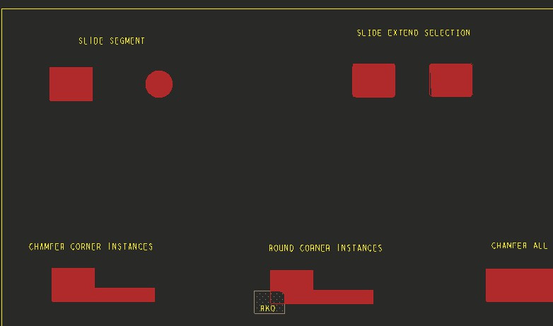
Begin by performing the most basic shape editing, the sliding of a segment, often referred to as the edge.
Sliding a Segment (shape edge)
1. Hover over the right side shape edge as shown below. (Your datatip may look different than what is displayed in this doc.)
2. Use the Tab key to cycle between the “segment” and “shape” element.
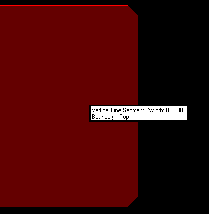
3. After pressing the Tab key a few times, finalise with the “vertical line segment” being highlighted as shown below
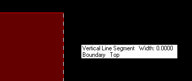
4. While hovering over the highlighted line segment, use right-click>Slide Segment and Slide the segment towards the right then make a left-click in background to clear the selection buffer.
5. Next we use an accelerated method to perform the same function. Look in Options and note the settings for “Click” and “Drag”.
6. With “Drag” currently set to “Slide”, hover over the same shape segment then hold left-click and drag to slide the segment.
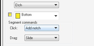
7. Change the “Click” value from Add Notch to Slide, then simply make a left-click on the segment to slide it. Similar to the behaviour in Etch Edit Application mode for sliding segments.
8. Perform any of the above steps on the Circular shape that is to the right of the rectangular shape.

Extended Segment Slide
In this step, we essentially perform a three segment slide operation on chamfered and rounded rectangles.
1. Use “Click” or “Drag” methods to perform the basic slide action that you learned in the last section.
2. Enable the Option “Extend Selection”
You can also use the SHIFT key to toggle the state of the “Extend Selection” option if you prefer.
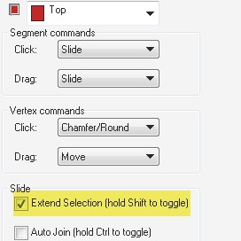
3. Select the straight section of the shape edge with a left-click, as shown in the next screenshot. Ensure the segment is highlighted as you begin to hover over it then slide it noting how the corners are maintained during the dynamic changes.
4. Disable the “Extend Selection” Option and slide the segment noting the behaviour is limited to just the single segment.

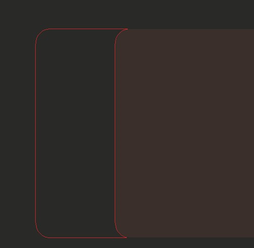
5. Perform the same steps to slide the edge of the rounded rectangle that is located to the right of the chamfered rectangle.
Adding a Notch
Adding a notch is a 2 step process where you select 2 points on a straight segment and extend inward or outward.
The example in this lab step is an “inward” notch.

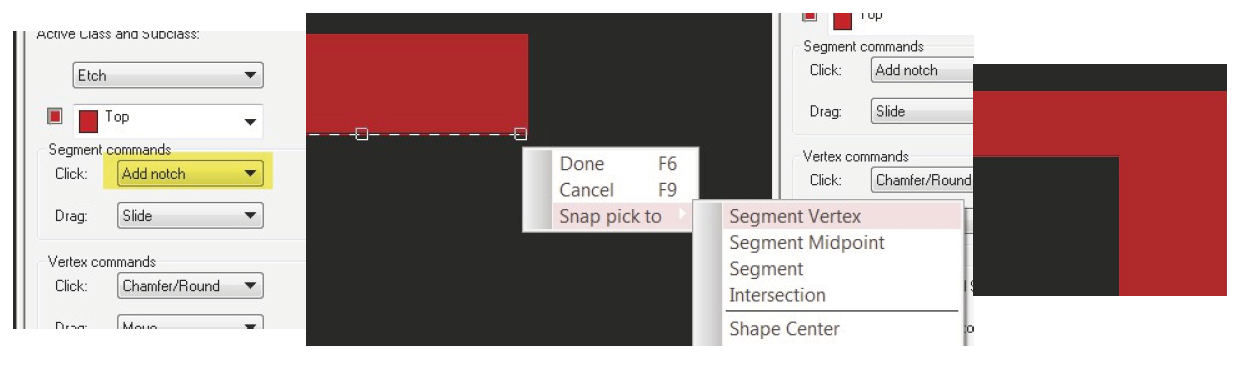
1. Hover over the bottom segment then use right-click>Add Notch. Position the two white squares that define the notch width then move your cursor to define the notch length.

2. Use “single click execution” mode to add the next notch. Ensure the “Click” Option is set to “Add Notch”. Based on the figures below, make your first left-click then right-click>Snap Pick to>Segment Vertex to add the second pick directly at the corner vertex location.
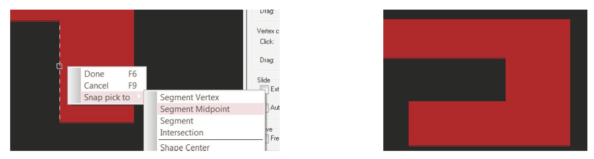
3. Add one more notch using the right-click>Add Notch method. Hover over the inside segment as shown in the left figure below then right-click>Snap Pick to>Segment Midpoint to place the first point at the midpoint of the segment. Add the second notch at the corner using right-click>Snap Pick to>Segment Vertex.
Move Vertex
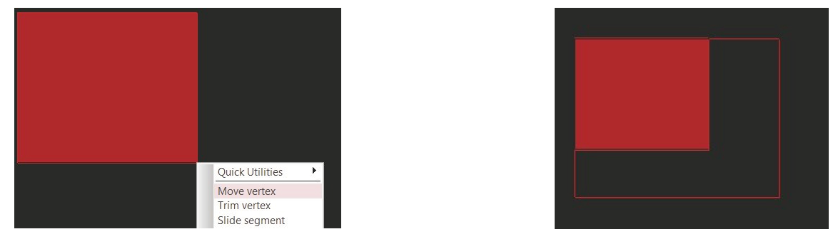
Selecting a vertex location on a shape boundary performs a two segment move.
1. Hover over the lower right corner of the shape, you will notice the change in style of the cursor.
2. Use right-click>Move Vertex
3. Move your cursor to increase the shape width and length
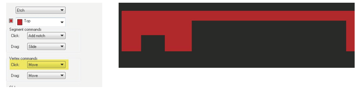
4. Perform the same action using a single left-click or Drag based on the “Vertex commands” setting shown below. Left-click on one of the inside boundaries of the notched shape and extend upwards and also to the right.
Chamfering Corners
This step begins on the second row of shape figures in the database
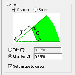
1. Adjust the settings as shown in the figure below
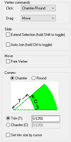
2. Hover over the top left corner then use right-click>Trim Corner.
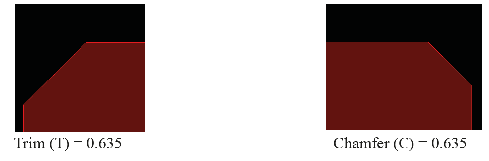
3. Referring to the bitmap at the bottom of Options: “T”, a value of 0.635 produces a 0.8064(5) chamfered length [Square root of (0.635 squared + 0.635 squared)] = 0.80645
4. Change the setting from Trim (T) to Chamfer (C) and use the same 0.635mm value
5. Make a single left-click on another 90 degree corner. The length of the chamfer should be 0.635mm as shown in the right image below.
6. Enable the setting “Set trim size by cursor”
7. Select another vertex location and adjust the chamfer by moving your cursor.

Rounding Corners
1. Adjust the settings as shown in the figure below; corners now set to “round”.
2. Disable the setting “Set trim size by cursor”
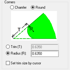
3. Hover over a corner vertex location then use right-click>Trim Corner

4. Make a left-click on another 90 degree corner to create a 0.635mm radius; continue changing corner types as you please.
5. Round the upper right corner of the route keepout shape. (Tip left click the keepout shape first, then left click on the corner).

Chamfering all Corners
1. Adjust settings as shown in the figure below
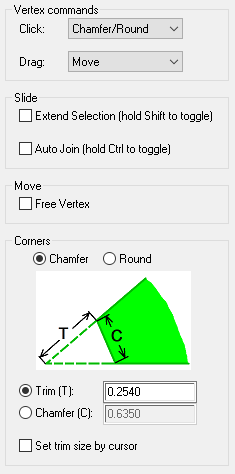
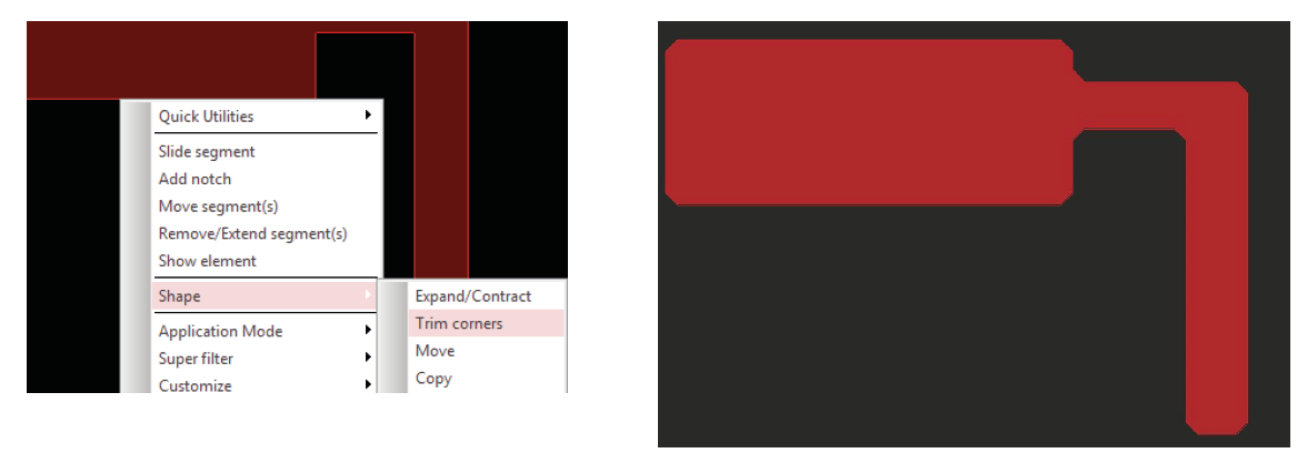
2. Hover over a line segment associated with the shape then right-click>Shape>Trim corners
Rounding all Corners
1. Pan right to the next shape and round all of its corners
2. Adjust the Options settings as shown below
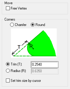
3. Hover over the shape boundary; use Tab key to ensure “shape outline” is active.
(Note the datatip display of “Dynamic Shape Boundary”)
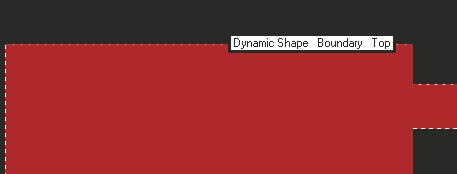
4. While hovering over the boundary, use right-click>Trim corners command.
(This is the second command in the list.)
5. You can use right-click>Remove / Extend Segments to remove segments.

Joining Segments
1. Adjust Options settings as shown in the figure below

2. Left-click the upper right vertical segment and slide to the left noting the behaviour.
3. Cancel during the command, or Oops after completing the command, to revert back to original shape
4. To join the segments, enable the Auto-Join setting in Options as shown below.
5. You can also use the Control key to toggle the state of the setting.
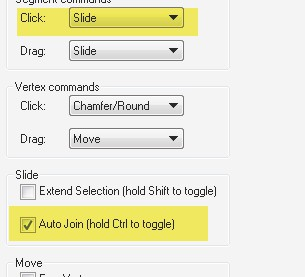
6. Left-click the same vertical segment and slide to the left noting the joining behaviour with the adjacent segments.
(If you experience an issue performing this step, use the Tab key to ensure you are acting on a segment and not the shape boundary.)
7. This should be the final result of your editing.

Sliding Multiple Segments
The goal of this step is to slide the entire right edge to the right while maintaining existing segment construction.
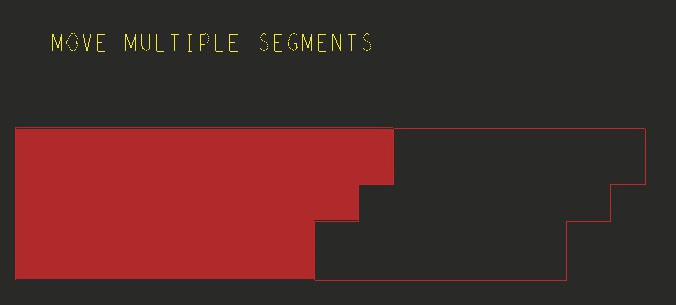
1. Left-click the 3 vertical segments on the right side of the shape. You can do this by depressing the Shift key then make 3 individual selections.
2. Hover over any one segment then right-click>Move Segments
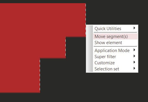
3. Move the group of segments to the right.

End of Lab
All content Copyright 2022 Parallel Systems Ltd.