
All content Copyright 2022 Parallel Systems Ltd.
1. If you don’t already have PCB Editor software running, start PCB Editor.
2. Open the file gloss.brd.
3. Select Display>Zoom>Fit from the top menu.
4. Select Setup>Colors from the top menu, and activate the Layers tab.
5. Left-click the Global Visibility Off button.
6. Select the Components folder.
7. Turn on Assembly_Top and Assembly_Bottom for RefDes
8. Select the Geometry folder.
9. Turn on the visibility for Design Outline (BrdGeo)
10. Turn on Assembly_Top and Assembly_Bottom (PkgGeo)
11. Select the Stack Up folder.
It is easier to see the reference designators with the wiring turned off.
12. Turn on only the following:
Pin for Top and Bottom and Via for Top only.
13. Left-click>OK to close the Colour Dialog form.
14. Select Manufacture>Auto Rename RefDes>Rename from the top menu.
The Rename RefDes form appears.
15. Check that Use Default Grid is selected.
16. Check that Rename ALL Components is selected.
17. Left-click on the Setup… button.
The Rename RefDes Setup form appears.
18. Make adjustments to this menu to match the next screen shot:
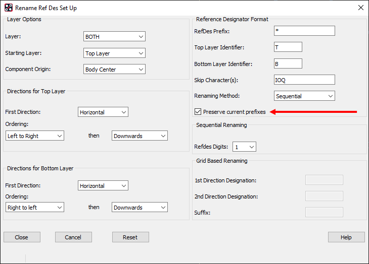
Notice that the Top Layer Identifier and the Bottom Layer Identifier fields have been blanked out because we don’t want extra suffixes added to show what side the component is placed on. The Preserve Current Prefixes check box has been enabled to use the same prefix that is currently assigned to the reference designators.
19. Left-click>Close to return to the Rename RefDes Setup menu.
20. Left-click>Rename to begin executing the automatic rename process.
21. Left-click>OK to close the Rename RefDes form.
22. Zoom in or pan your view to inspect your results.
23. Select File>Save As from the top menu.
A browser form appears.
24. In the File Name field, enter:
release
25. Left-click>Save in the file browser, OK to overwrite.
The file release.brd is saved to disk.
You will overwrite this version of your design while preparing it for final output phases.
26. Zoom in to view a component of your choice.
27. Check that the Application Mode is General Edit, towards the lower right of the Status Bar at the bottom of the PCB Editor window to check. If not, select Setup>Application Mode>General Edit from the top menu.
28. Check that Text is enabled in Find, then move the mouse over a Reference Designator in the canvas, use the Tab key if the Reference text is not being highlighted, and right-click>Text Edit, enter the new value for a valid Reference Designator in the Text Edit box, say U99 (starts with a letter, ends with a number, no spaces), and left-click>OK to set the new reference designator value.
IF the name chosen already exists, a message in the PCB Editor command window confirms that the name is being swapped with the reference for another component. This feature prevents duplicate names from being accidentally created.
29. Select File>Save from the top menu.
30. Left-click>Yes to confirm the overwrite.
The file release.brd is written to disk.
End of Lab
All content Copyright 2022 Parallel Systems Ltd.