
All content Copyright 2022 Parallel Systems Ltd.
Start PCB Editor from:
Start (Windows Icon) >Cadence PCB 17.4-2019>PCB Editor 17.4
The PCB Editor Canvas opens.
1. Select File>Open from the PCB Editor main menu.
2. If necessary, set the File Type for Board (*.brd)
3. Use the Browse button to navigate to the C:\OrCAD_Training\PCB_Designer\project\Drafting directory, select the drafting.brd file and left-click on Open
(Yes to save if you already had a board open from the previous labs)
4. Enter General Edit Application Mode with right-click>Application Mode>General Edit in the design canvas.
5. Check the Find Filter to ensure only “Lines” “Other Segs” are enabled
The database is set up with a series of small exercises to demonstrate each command, start at the top left and work to the right….

Extending a Segment
This command allows users to extend line and arc segments to a projected intersection point. Once the objects are selected, the two objects are temporarily extended and highlighted to show the possible intersection points, and the user is prompted “Select intersection point.” At this point the command can continue by extending more lines and arcs, or finish with right-click>Done / Cancel.
This command can also be invoked from the RMB – General Edit mode after preselecting a line or arc segment, at which point the user will be prompted for an object to intersect, as well as an intersection point. Once this is specified, the command exits. (Changes can be rolled back by Edit>Undo, if desired.)
As you go through each exercise, vary the methods by which you access the commands. For simplicity, the context based access will be used in this exercise.
1. Hover over the left-most line segment in the area labelled “Extend” as shown below.
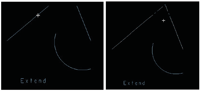
2. Right-click>Drafting>Extend Segments on that segment. The command line will prompt you to select another object.
3. Left-click on the other line segment. A “temporary” extension will be drawn for each possible interaction between the two lines (in this case, there is only one). Left-click on the temporary connection or right-click>Done to finalize the modification.
4. While hovering over the right-most segment, use the right-click to access the same command again, this time left-click on the arc as the second object. Note that there are now two possible interactions:
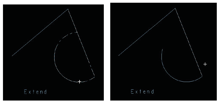
As prompted on the command line, left-click the bottom connect point, and that option will be finalized. Note that the right-most segment remains selected if there are any further interactions needed. Left-click somewhere in open space to clear the selection buffer.
Trimming a Segment
Scroll right to the next group of objects – “Trim”.
This command allows users to remove portions of line and arc segments that extend beyond specified intersection points.
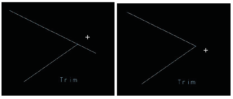
In this example, the smaller segments that go beyond the intersection point will be removed.
The click sequence is to:
a) Identify the intersection point, and then
b) Identify the segment portions to be removed.
1. Right-click>Drafting>Trim Segments on one of the lines, then left-click on the other segment to identify the intersection point (where they cross):
(it is not necessary to actually pick the intersection point)
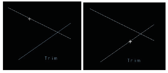
2. Then left-click on the two smallest segments that leave the intersection (the two on the right), and each one will be removed after selection. Right-click>Done when complete.
Add Tangent Lines
Scroll right to the next group of objects – “Add Tangent”.
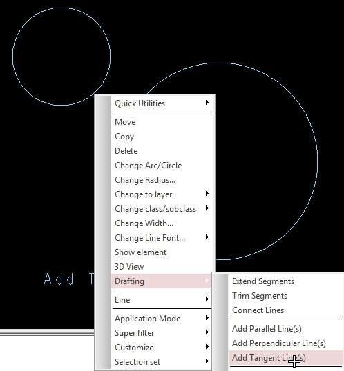
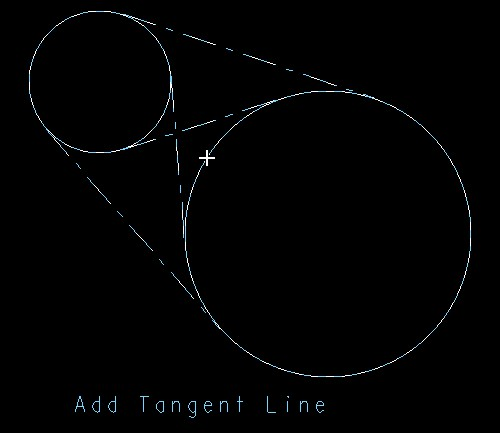
This command allows users to add one or more lines tangent to existing circles or arcs. The user selects two arcs or circles and temporary lines are created representing all possible tangent lines between the two objects. The user is then prompted to select which ones to keep.
1. On one of the circles in the design, right-click>Drafting>Add Tangent Line(s).
2. Now left-click on the other circle, all possible tangent lines between the two are drawn:
3. Select which of the possible lines you would like to keep by left-clicking on them:
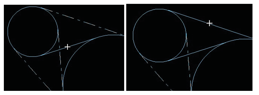
4. Right-click>Done to remove any remaining “temporary” lines:
Delete by Line / Rectangle
Scroll right to the next group of objects – “Delete by Line” and “Delete by Rectangle”
These commands allow users to remove the portion of lines, arcs, and segments lying to one side of a user-specified cut line, or inside a user-drawn rectangle, respectively. Users wishing to restrict the angle of the cut line to multiples of 45 degrees can do so via the “Line lock” setting in Options.
1. Window drag a box to pre-select the entire group of lines on the canvas in the “Delete by Line” group.
2. Hover over one of the lines and right-click>Drafting>Delete by Line and draw a line with the mouse through the selected lines:
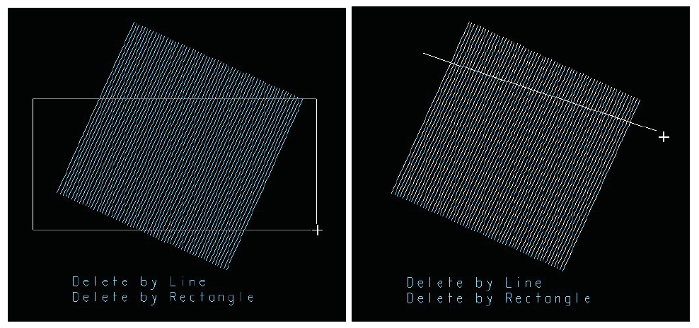
3. Left-click to pick which side of the line the portion of the objects should be deleted (select a point above the line, for example):
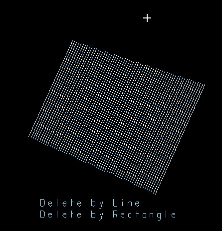
4. Use Edit>Undo to reset the group of lines back to their original size, we will use these to test the Delete by Rectangle command.
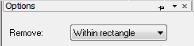
5. Re-select the group of lines and then hover right-click>Drafting>Delete by Rectangle. Check Options and ensure the Remove option is set as follows:
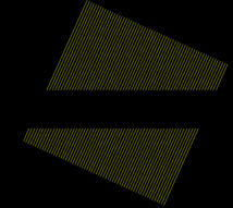
6. Left-click, move the mouse and left-click to draw a rectangle through the group of lines ensuring to cross the complete area, when complete the portion inside the area you drew will be deleted.
7. Use Edit>Undo to reset the groups of lines back to their original state then re-select them and use right-click>Drafting>Delete by Rectangle, this time check Options and ensure the Remove option is set as follows:
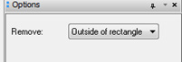
8. Left-click, move the mouse and left-click to draw a rectangle through the group of lines, be sure to cross the complete area. When complete the portion outside the area you drew will be deleted.
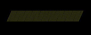
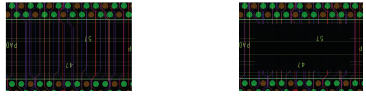
Note that these commands are not limited to objects on documentation layers: clines (by line) and vias and clines (by rectangle) can also be selected.
For example:
Offset Copy
Scroll right to the “Offset Copy” group.
This command allows users to make multiple copies of a variety of objects offset from the original(s) by a specific X and/or Y value.
Options allows entering of X and Y offset values, the number of repetitions, and width / font values.
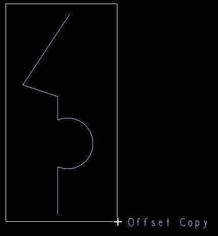
1. Window drag a box to pre-select the entire group of lines on the canvas in the “Offset Copy” area
2. Hover over an element of the selected lines and right-click>Drafting>Offset Copy
 :
:
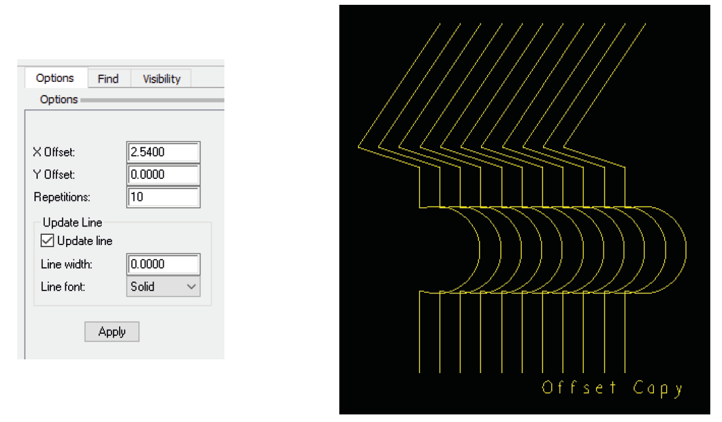
3. In Options, set the offsets and number of copies and left-click Apply:
Offset Move
Scroll left and down to the next object – “Offset Move”
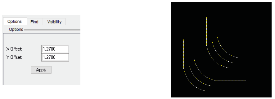
This command allows users to move a variety of objects by a specific X and / or Y offset.
Options allows entering X and Y offset values.
1. Window drag a rectangle over the upper group of three lines
2. Hover over one of the selected objects, and right-click>Drafting>Offset Move
3. In Options, set +1.27mm for X Offset and +1.27mm for Y Offset and left-click on Apply.
The lines will be moved to the upper right.
4. Right-click>Done to accept the change.
Relative Copy and Move
Stay with this group for the next section.
This command allows users to make copies of a variety of objects mirrored from the original(s) relative to a line.
Options control the line around which the copies should be mirrored.
Once objects are selected, the user is prompted for an origin point. Then the copies become dynamically visible in the canvas, and the user is asked to make one further pick to establish the actual point for the new objects.
Relative Move works the same as Relative Copy, except that it provides a Move rather than a Copy operation.
1. Window drag a box to select the entire group of six lines from the previous “Offset Move” section.
2. Hover over one of the lines and right-click>Drafting>Relative Copy.
3. Select the origin and set Options as shown in the next screen shots:
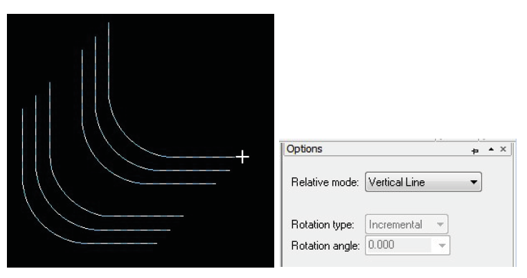
4. A vertical “mirror line” will appear, and you can slide the mirror image left and right, use left-click to place the mirrored objects:
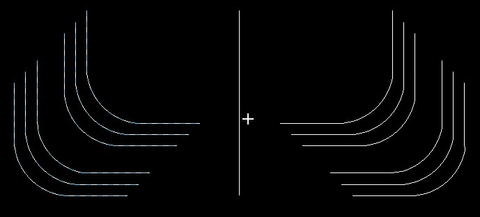
5. Now, window drag a box to select the entire pattern.
6. Hover over one of the lines and right-click>Drafting>Relative Copy.
7. Select the origin as shown, and set Options “Relative Mode” to Horizontal:
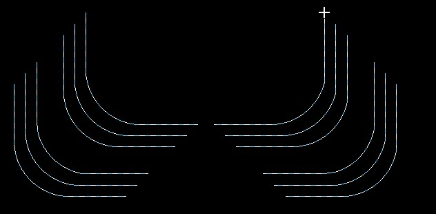
8. This portion can now be mirrored upwards to generate a complete pattern:
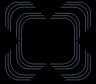
Connect Lines
Scroll right to the next object group, “Connect Lines”
This command provides the ability to add lines connecting the endpoints of existing lines and arcs. With as segment selected, hover-over and right-click>Drafting>Connect Lines, the user is then prompted to pick the next object, and temporary lines are inserted representing all possible lines connecting the end points of the two objects; the user can then pick the required one.
1. Starting on the lower right, hover over the segment and then right-click>Connect Lines:
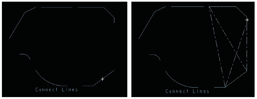
2. Pick the line in the upper right as the 2nd Segment; then select the right-most line as the correct connecting segment:
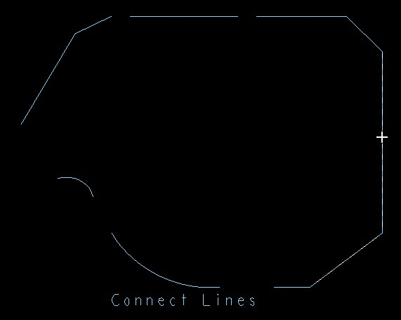
3. Using the same methodology at each gap, go around the entire boundary and connect all the segments:
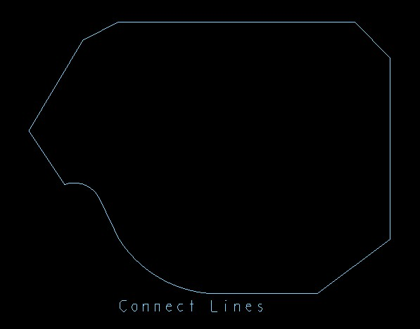
Hint: Pure vertical or pure horizontal lines are better connected with right-click>Drafting>Extend Segments
Hint: Zoom In!
Add Parallel Lines
Scroll across to the Add Parallel Lines / Add Perpendicular lines section.
This command facilitates the creation of lines parallel to existing lines. The mouse is used to select which side and Options is also used to specify the distance between the lines and the number of lines required.
1. Hover over the line and right-click>Drafting>Add Parallel Line(s) on the line. In Options, select a spacing of 2.54mm and 4 as the number of lines:
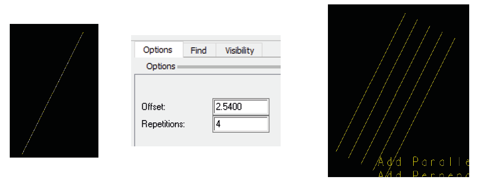
2. Now left-click in the empty space to the right of the line to indicate the side/direction for the Add.
Add Perpendicular Lines
Stay in this example for the next.
This command allows users to add a line perpendicular to another line already in the design. After a pick is made, a “rubber band” line appears on the cursor, with the reference object or start point as its first end point, and then the user specifies either the end point or another reference object. At this point the user can continue by adding more lines or finish with right-click>Done.
1. Hover over the right-most line and right-click>Drafting>Add Perpendicular Line(s):
2. A temporary line is placed on the cursor. Using the mouse, you can control which side, the length of the line, and change the placement of the line along the reference line:
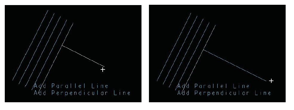
3. Then left-click to set the end point and create the perpendicular line.
 End of Lab
All content Copyright 2022 Parallel Systems Ltd.