
All content Copyright 2022 Parallel Systems Ltd.
1. In the Project Manager, right-click on the TRNG.OLB and select New Part.
The New Part Properties dialog box appears.
2. Complete the form as shown in the graphic that follows.
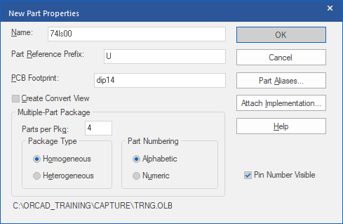
Name: 74LS00, Part Reference Prefix: U, PCB Footprint: DIP14, Parts per Package: 4,
Package Type: Homogeneous, Part Numbering: Alphabetic
4. Left-click>OK.
Note
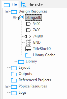
When finished, the TRNG library window should look like the next example.
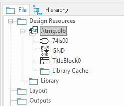
The Part Editor automatically displays a part Bounding box five grid spaces square. All part graphics will fit within the dotted boundary which will expand as required. Note that the Bounding box dotted outline will not normally be visible in the Capture schematic, and that pins are attached to the Bounding box, so it should always remain “on grid” for placing pins.
5. If not already maximised, maximise the Part Editor window, then select View>Zoom>All (or left-click the Zoom to All icon in the toolbar).
6. Left-click the Place arc icon in the toolbar, or select Place>Arc from the menu.
To create an arc, you must enter three mouse clicks, as shown in the next graphic as an illustration of the process, follow steps 7 to 10 for details.
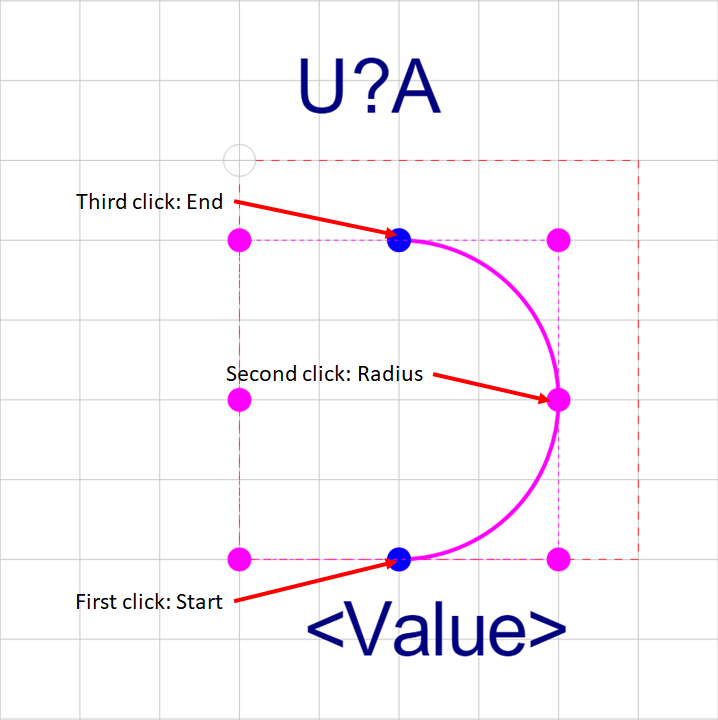
7. The first left-click should be on the bottom edge, near the centre of the edge of the default bounding box (this will be the centre point of the arc).
8. Left-click two grid points above and to the right to establish the radius for the arc.
9. Move the cursor upwards to line up with the staring point and 4 grids above it to form a semi-circle, left-click to end the arc.
10. Press Esc once to exit drawing mode.
11. Select Place>Polyline from the menu, or left-click the Place polyline icon, and add lines to complete the shape, as shown below.
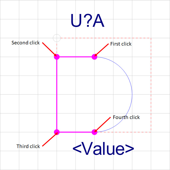
12. Right-click and select End Mode from the pop-up menu.
13. Now press the Esc key to exit polyline mode, and Esc again to deselect the polyline.
14. At this point, your graphic should resemble the following picture:
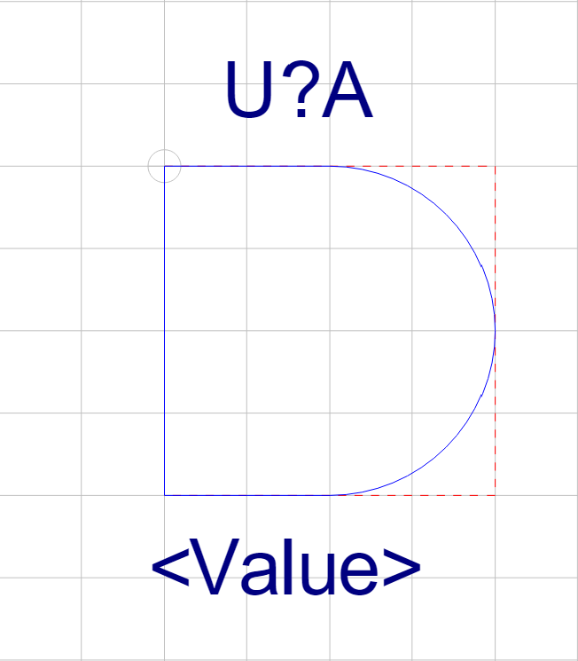
The bounding box may already be the size of the symbol, if necessary, left-click and drag the bounding box outline to fit around the symbol details, check that the “snap to grid” icon is not red, otherwise it will be possible to have the Boundary box off-grid and then place pins off grid. Generally, the Bounding box should touch the edges of the part graphics, otherwise, the appearance of the part might be a little “odd” when placed in the schematic.
15. Press Esc to deselect the bounding box.
16. Select File>Save.
17. Left-click the Place pin icon, or use Place>Pin from the menu.
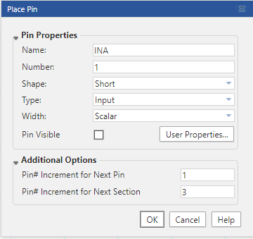
18. Enter the information shown in the next picture:
(Name: INA, Number: 1, Shape: Short, Type: Input)
19. Left-click>OK.
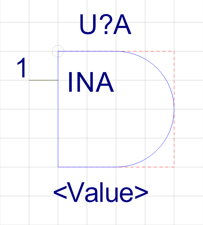
The pin image attaches to the boundary box. As you move your cursor, the pin snaps to grid points along the boundary edges.
20. Position it as shown in the following picture, left-click to place it.
Do not double-click when adding a pin, as this places two pins at the same location.
21. Move the cursor and notice that a second pin is now attached and ready for placement.
22. Left-click to add a second pin two grids below the first pin.
Notice that the pin number automatically increments, the pin name will be changed later.
23. Place a third pin on the right side, as shown in the graphic that follows.

24. Press the Esc key twice.
25. Left-click>Edit Pins at the lower right.
26. Set the Pin options as follows:
Rename Pin 2 to INB and Pin 3 to OUT, at the left;
Set the Pin Group to 1 for the INA and INB Pins;
Change the OUT Pin Shape to Short-Dot and Pin Type to Output (Double-click the Pin Shape and Pin Type cells to get the drop-down activated for selection);
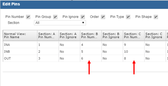
Check / Change the Pin Numbers for the sections:
INA > 1 4 9 12
INB > 2 5 10 13
OUT > 3 6 8 11
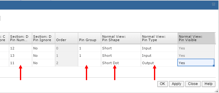
27. Left-click>OK to close the Edit Pins form
(OK any message about duplicate Pins)
28. Go to Place>Pin again and add the GND Pin as shown in the following screen shot:
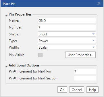
29. Left-click>OK and left-click to place the Pin at the bottom of the drawn graphics.
30. Move the mouse to the top of the drawn graphics and left-click again to place the Pin.
(Left-click and drag the Reference U? and the <Value> text values away from the edges of the drawn graphics to make room for the Power Pins)
31. Left-click>Edit Pins and change the Pin Name of Pin 14 to VCC
(You could edit the Pin Name and Pin Number if you missed any of these settings when adding the GND Pin, should be VCC and 14 once edited)
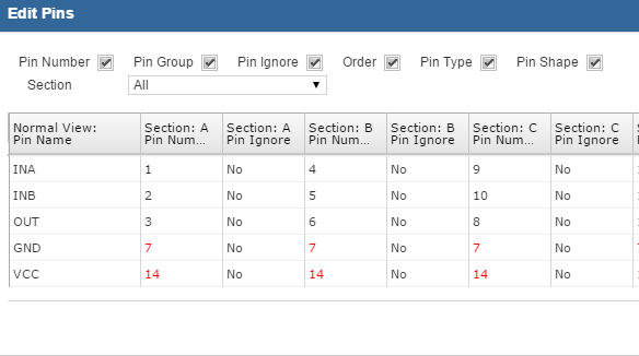
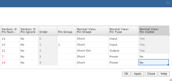
The “duplicated Pin Numbers, 7 and 14, will be displayed in Red.
Note that the Power Pins have not been displayed in this case but it would be more common practice to display all of the Pins to ensure correct connections in the schematics.
32. Left-click>OK
The part should now look like this:
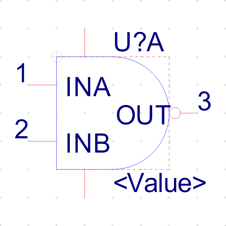
33. Select File>Save
34. Move to the Part Properties section on the right hand side and left-click the “+” icon
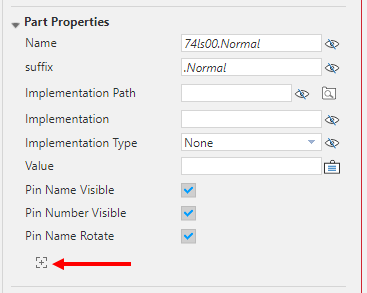
35. Set the Name of the Property to PART_NUMBER and the Value to AB12345678 (or some other value)
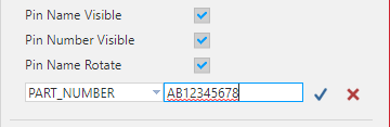
36. Left-click the “tick” to add the new property.
37. Left-click the Display Property icon – looks like an “eye” with a diagonal line through it (for not displayed) – and select Value Only from the drop-down.
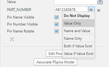
The property value is now visible on the part. When this part is used in a schematic, the PART_NUMBER property value will be visible.
Note
If properties are being defined for use with and PCB Editor products, DO NOT use any spaces in any of the property names. Dashes ( – ) or underscores ( _ ) are acceptable.
Note
A required property for PCB Editor for all parts is a property called CLASS. Each part must then have a CLASS property value of either:
• IO (for Connectors)
• IC (for standard parts like memory, etc.)
• DISCRETE (for all discrete parts such as resistors, capacitors, etc.)
• MECHANICAL (for any mechanical parts to transfer from schematic)
38. Move to the Part Properties section on the right hand side again and left-click the “+” icon
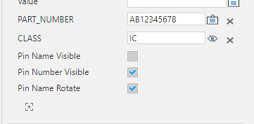
39. This time Name the new property CLASS and set the Value to IC. (This property won’t be displayed)
40. To hide the Pin Names, move to the Part Properties again and un-check the box for Pin Name Visible.
41. Select File>Save

End of Lab
All content Copyright 2022 Parallel Systems Ltd.
Optional Section
Important
This method should NOT be used if each part is unique since any properties assigned will be common to all of the aliases !
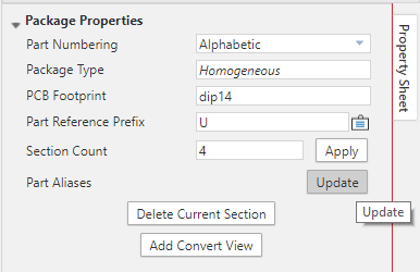
1. Move to the Package Properties section on the right hand side and left-click>Update for Part Aliases.
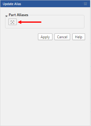
2. In the Update Alias window, left-click the “+” to add a New Alias
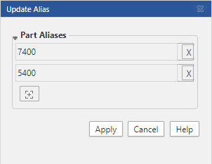
3. Left-click in the alias box, enter 7400 and left-click the “tick” to set the value.
4. Repeat this step again adding 5400 to the list.
The list of aliases should resemble the following picture.
5. Left-click>Apply
6. Select File>Save.
7. Select File>Close
The finished TRNG library window should look similar to this, assuming that the Part
Aliases have been added.
End of Lab
All content Copyright 2022 Parallel Systems Ltd.