
All content Copyright 2020 Parallel Systems Ltd.
1. If a library is not still open in Capture, select and open the TRNG.OLB library you were working with.
2. Highlight the library name and from the right-mouse button pop-up menu select New Part.
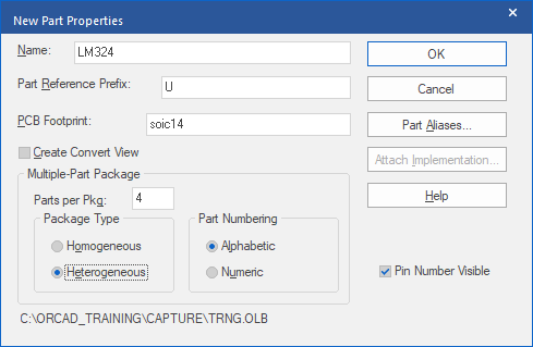
3. Enter the information as shown above.
4. Left-click>OK.
5. Set your window to full, then select View>Zoom>All (or left-click the button in the toolbar) to adjust the view.
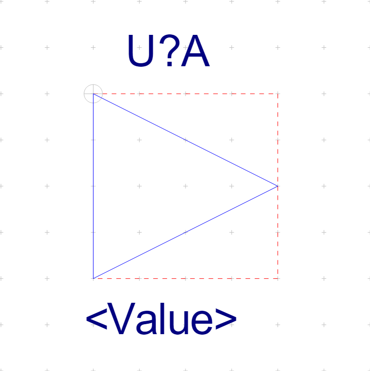
6. Using the Place>Polyline command from the top menu, or use the toolbar button, draw a triangular graphic as shown in the next image.
Remember to use the Shift key while drawing in order to angle the poly-line.
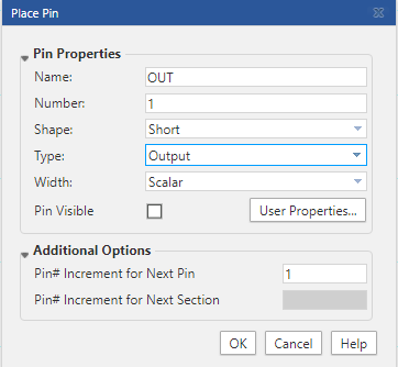
7. Left-click the Place Pin button.
8. Enter the information shown in the following picture, then left-click>OK.
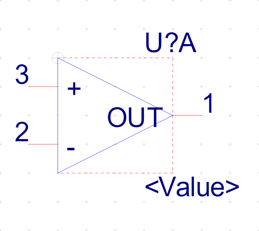
9. The pin image appears, attached to the cursor. Position it as shown in the following picture, and left-click to place it.
10. Continue to add pins to make the follow image.
Next pin: Name ( – ), Number ( 2 ), Type ( Input )
Next pin: Name ( + ), Number ( 3 ), Type ( Input )
11. Select Place>Pin.
12. Enter the information shown in the following picture, then left-click>OK.
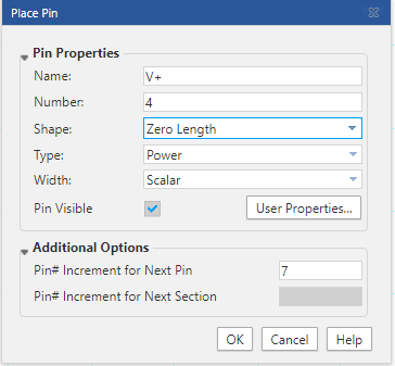
13. Place the V+ Power pin, pin number 4, at the top edge of the bounding box.
14. Place the V- Power pin, pin number 11, at the bottom edge of the bounding box.
(If you used the increment of 7 shown, you can place the Pin and then change the name on the right hand side in Pin Properties)
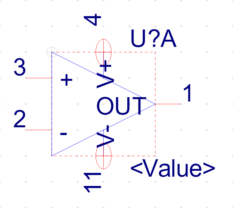
After placing the power pins, add a line between the pin and the triangle outline, if required. Turn off the “Snap to Grid” to get the line and the triangle to meet as desired, turn the “Snap to Grid” back on as soon as the lines have been placed, otherwise other objects in the library could be placed off grid which could be undesirable.
15. Left-click the “+” in Part Properties, and set the Name to PARTGROUP, leave the Value field blank and left-click the “tick” to add the property.
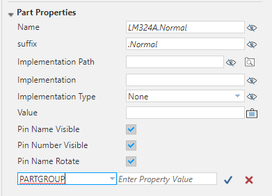
16. Left-click on the Display Property icon, looks like an “eye” with a diagonal line through it for the PARTGROUP property and select Value Only from the list.
The part should look like the following picture.
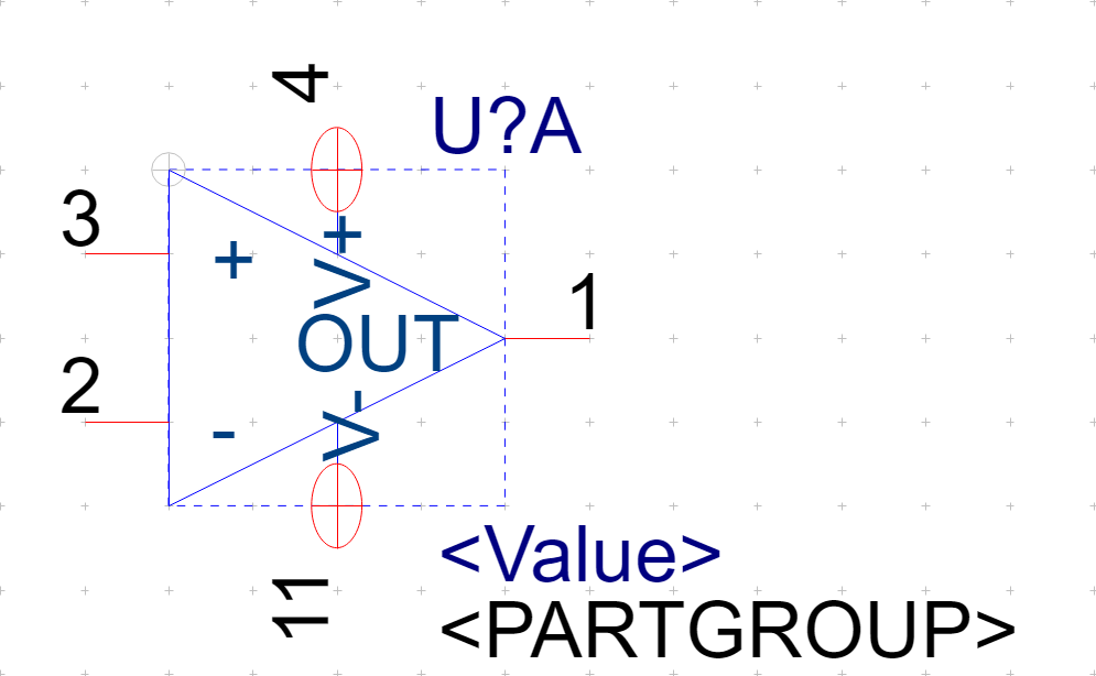
17. Select File>Save.
18. Window select all of the objects in the “A” part and Control+C, or Edit>Copy, then Control+N or View>Next Part, to get the next part. Then use Control+V, or Edit>Paste, to paste the copied objects – OK to “replace all” if prompted.
19. Using the skills you learned above, create the next sections in the package. What makes this section unique from section one is that the next 3 “gates” do not have the V+ / V- pins, so just delete them from the “B” section and then copy that to the other sections. (NOTE: this symbol will NOT work with PSpice)
Please refer to the following list for the pin names and numbers in the other “gates”.
Gate B: + = 5, – = 6, OUT = 7
Gate C: + = 10, – = 9, OUT = 8
Gate D: + = 12, – = 13, OUT = 14
20. Close and Save the library part.
21. File>Close the library.

End of Lab
All content Copyright 2020 Parallel Systems Ltd.