
All content Copyright 2022 Parallel Systems Ltd.
1. In the project window, open the part library file TRNG.OLB.
2. Select Design>New Symbol, or right-click on the trng.olb entry in the Project Manager and choose New Symbol.
The New Symbol Properties dialog box appears, as shown in the following picture:
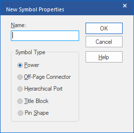
3. Name the symbol VCC, set the Symbol Type to Power, and left-click>OK.
4. Select View>Zoom>All to see the symbol graphics, which should resemble the following picture:
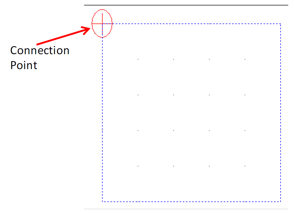
The symbol graphic consists of a connection point at one corner of the graphic bounding box. Power symbols have a maximum of one connection point.
5. Drag the connection point to the bottom centre of the bounding box.
6. Draw a vertical line one grid long, up from the connection point.
7. Draw a circle (or an arrow shape) on the top of a line drawn from the connection point. If this requires the circle to be placed off-grid, disable snap-to-grid by clicking the Snap To Grid toolbar icon (so that it turns red) or press Control+T. Then draw (or Move) the circle off-grid as needed. Zoom in to help with the placement, if necessary.
Caution
Be sure to turn grid snap back on by clicking on the Snap to Grid toolbar icon again or by pressing Control+T, or using the Toolbar icon.
8. Using the techniques you learned in previous labs, make the NAME Part Property value visible from the Part Properties.
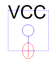
9. Position the symbol name so it is located in the upper left corner of the bounding box. The symbol should resemble the following example for a circle.
10. Save the symbol and close it.
End of Lab
All content Copyright 2022 Parallel Systems Ltd.