
All content Copyright 2022 Parallel Systems Ltd.
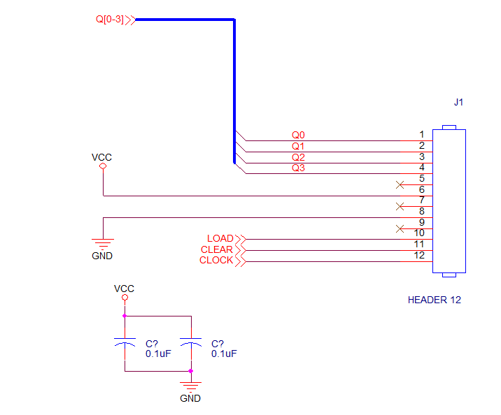
1. Take a moment to examine the following schematic, use this example as a guide as you complete the steps in this lab.
2. Make sure the schematic window is active, and left-click the Place Part icon, or press the P key.
3. In the Place Part window, left-click on plus sign (+) to the left of Search for Part.
The Part Search portion of the Place Part tab opens.
4. The Library Path field, located at the bottom of the Search for Part section, should already show the training library installation path
C:\OrCAD_Training\Capture\library
If not, use the Browse button to set this path.
5. In the Search For field, enter:
header*
Capture searches all libraries for any parts that begin with the word “header”.
6. Left-click the Part Search icon.
Capture locates many different headers in a CONNECTOR library.
7. Scroll down and double-click on the HEADER 12/Connector.olb entry in the list.
The CONNECTOR library is added to the Libraries list in the Place Part window, and the HEADER 12 part is automatically selected and “floating” on your cursor.
8. With the connector still attached to your cursor, right-click>Mirror Horizontally
The connector pins should now be facing to the left.
9. Right-click again, and Edit Properties
10. In the Edit Part Properties window, enter J1 into the Part Reference field.
11. In the PCB Footprint field enter CONN12 and left-click>OK.
12. Left-click to place the connector in the design. (Towards the right hand side of the page)
13. Press Esc to end Place Part mode.
14. Press Esc again to deselect the connector.
15. Select File>Save from the top menu.
You mirrored the connector horizontally, and assigned a reference designator to it before placing it in the design. You could also have done this after the part was placed.
16. If the Part Place tab is closed, left-click the Place Part icon in the schematic toolbar, or press the P key
17. Left-click on the Add Library button.
The Browse File window appears.
18. In the Look in field, navigate to the library directory:
C:\OrCAD_Training\Capture\library
(This path is specific to the training files)
19. Select the DISCRETE.olb library file and left-click>Open.
The DISCRETE.OLB library is added to the Libraries list in the Place Part window, and all the parts in this library are listed in the Part List.
20. In the Part field, enter:
cap
Observe that each character you enter is used to search the Part List for all matching entries.
21. Select the CAP part with a left-click and press Enter to attach it to the mouse cursor, move the mouse into the schematic canvas and right-click>Edit Properties
22. In the Part Value field, enter 0.1uF.
23. In the PCB Footprint field enter SM_1206.
24. Left-click>OK.
25. Left-click to place the capacitor in the design, towards the left hand side of the page.
26. Press Esc to end the command, and press Esc again to deselect all parts.
27. Select File>Save from the top menu.
The value and PCB Footprint property values were assigned before placing the part in the design. This could also have been done this after the part was placed.
28. Place the cursor on the capacitor, left-click to select, and press and hold Control+left-click, and drag a copy of the capacitor to a new location.
29. Press Esc.
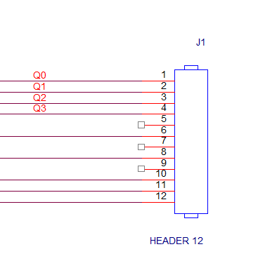
30. Left-click the Place Wire icon, or press W, and add wires as shown in the next picture:
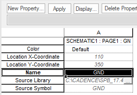
31. Save the design.
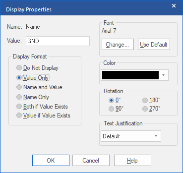
32. Left-click the Place Net Alias icon, or press the N key, and add net aliases as shown, Q0, Q1, Q2 and Q3
Note
After you add a net alias, an easy way to specify the next net alias you want to assign is to right-click and select Edit Properties from the pop-up menu (or use CTRL+E). Then enter the new net name in the Edit Properties window.
33. Save the design.
34. Use the Place No Connect icon to place No Connect symbols on the three unconnected pins of the HEADER 12 part.
35. Press Esc to exit the Place No Connect command.
36. Save the design.
37. Left-click the Place Power icon.
The Place Power window appears.
38. In the Libraries field, check that, at least the capsym library is selected in the list, if not, left-click on the CAPSYM entry to select it.
39. Scroll down, left-click the VCC symbol to select it and left-click>OK.
40. Add the VCC symbol to the schematic. You may place as many VCC symbols as required (or they can be copied later).
41. Left-click the Place Ground icon.
42. Left-click the GND symbol, left-click>OK, and place as required.
43. Press Esc to exit the command, and Esc again to deselect all parts.
To move a power or ground symbol, press and hold the left mouse button and drag the symbol to a new location.
44. Add or adjust wiring to connect the power and ground symbols.
45. Save the design.
46. Select the GND with a left-click then right-click>Edit Properties.
47. When the Property Editor window opens, left-click on the Pivot button to get the Property names listed in the left hand column, if they are not already listed on the left, and then look for the Property called Name and select the row as shown in the next screen shot.
48. Left-click the Display button, just above the Property line.
49. The Display Properties window will open, choose Value Only and left-click>OK.
The Display Properties window will close.
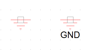
50. Close the Property Editor tab to apply the change, “Yes / OK” any “save messages”. View the following image, before the GND name is not displayed, after the display change it is displayed.
51. Left-click the Place Bus Entry icon. (Or Place>Bus Entry from the top menu, or press E)
A bus entry symbol attaches to your cursor.
52. Left-click to add bus entries to the ends of the Q0 through Q3 signals on the HEADER 12 connector (as shown in the next picture).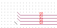 Note
Note
Use the F4 key to repeatedly place the bus entry wire. Place the first Bus Entry symbol, select the Esc key, then F4 to repeat another symbol.
53. Left-click the Place Bus icon (Or Place>Bus from the top menu or press B)
54. Hold the Shift key, and left-click to add a bus wire to the ends of the bus entries (as shown below).
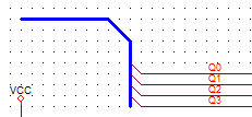
55. Save the design.
Note
Hold the Shift key while drawing any wire or polyline to add diagonal segments. Otherwise, all segments are added orthogonally.
56. Left-click the Place Off-page Connector icon  (Or Place>Off-page Connector from the top menu)
The Place Off-Page Connector window appears.
57. In the Libraries list, left-click on CAPSYM.OLB, then select
OFFPAGELEFT – L from the list above.
58. In the Name field (at the bottom), enter:
Q[0-3]
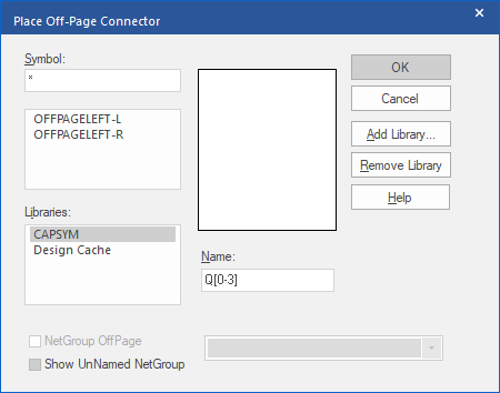
59. Left-click>OK.
The off-page connector attaches to your cursor.
60. Press the R key to rotate the symbol. Do this twice to spin it 180 degrees.
61. Left-click to attach the off-page connector to the end of the bus wire (as shown in the next graphic).
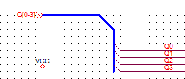
62. Press Esc to exit the command, and Esc again to deselect the off-page connector.
63. Left-click the Place Off-page Connector icon, and repeat this process to add off-page connectors to the LOAD, CLEAR, and CLOCK nets also.
Note
An easy way to change the name of the next off-page connector you want to add is to right-click and select Edit Properties from the pop-up menu.
64. Left-click>Zoom to All icon. Your finished page should resemble the following image.
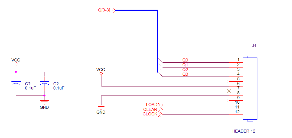
65. Select File>Save.
66. Select File>Close, and No to close the window.
67. In the Project Manager window, look at the list of parts under the Design Cache folder.
This list represents all the parts that were added to page one of this design.
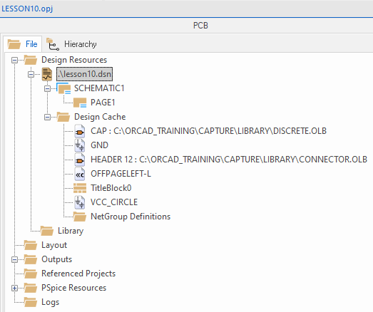
68. Left-click the minus sign (–) to the left of the Design Cache folder to collapse the display.
End of Lab
All content Copyright 2022 Parallel Systems Ltd.