
All content Copyright 2022 Parallel Systems Ltd.
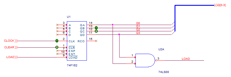
Take a moment to examine the above schematic. This is a modified version of the Lesson 8 schematic. Use this example as a guide for this lab.
1. Select File>Open>Project from the top menu.
2. In the Open Project window, navigate to the directory:
C:\OrCAD_Training\Capture\Lesson8
3. Highlight Lesson8.opj and left-click>Open.
The Lesson8 project opens in another tab in the Project Manager pane.
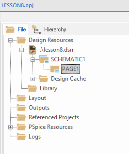
4. If necessary, Left-click the plus signs (+) to expand the contents of the .lesson8.dsn file until you see the PAGE1 entry.
5. Left-click on PAGE1 of the SCHEMATIC1 folder.
6. Select Edit>Copy from the top menu, or use Control+C to copy the page
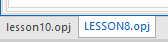
7. Left-click and select the Lesson10 project tab and left-click on the SCHEMATIC1 folder.
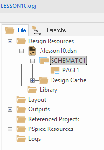
8. Select Edit>Paste from the top menu, or use the Control+V
9. Since PAGE1 already exists, an error message about “Page in Use” is displayed and the option to use another page name is shown.
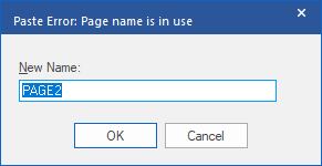
PAGE2 is the default and fine for this lab so, left-click>OK
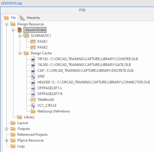
(PAGE1 of the Lesson8 project now appears in the SCHEMATIC1 folder of the Lesson10 project as PAGE2)
10. Left-click the Lesson8.opj tab in the Project Manager pane to activate it and select File>Close. If prompted, left-click>No to discard all changes.
11. In the Lesson 10 Project Manager window, left-click on .\Lesson10.dsn and select File>Save.
Using the instructions that follow, complete the schematic page to resemble the next picture. (Don’t be concerned about the DRC Markers that were copied over from the source page)

12. Double-click on PAGE2 of the Lesson10 design.
(This is the page just copied from the Lesson8 project.)
13. Add bus entries to the Q0 through Q3 nets.
Press the R key to rotate the bus entry symbols into the correct position.
14. Add a bus wire to bundle the Q0 through Q3 bus entries together.
Remember to hold the Shift key to draw a diagonal bus wire.
15. Add an off-page connector to the end of the bus wire.
Use the OFFPAGELEFT-R symbol from the CAPSYM library and rotate it into the correct position. Be sure to name the off-page connector using the correct syntax.
16. Add off-page connectors to the CLOCK, CLEAR, and LOAD nets also.
You will need to use both types of off-page symbols, and each one will need to be named and rotated.
17. Delete the Net Aliases for CLOCK, CLEAR and LOAD from the wires that the Off-Page connectors were added to.
18. Zoom in to the title block and double-click on it to edit the Properties.
19. In the Properties tab that opens, locate the Title property and change the value to Lesson 10 move the mouse to the tab for the properties page and right-click>Close, “Yes / OK” any “save” messages
20. Left-click the Zoom to all icon.
21. Select File>Save.
22. Select File>Close to close the window.
23. Left-click the plus sign (+) next to the Design Cache folder, and examine the list of parts. Observe that this list now includes the parts contained in the copied page also.
End of Lab
All content Copyright 2022 Parallel Systems Ltd.