
All content Copyright 2022 Parallel Systems Ltd.
In this section, the wires and buses will be grouped into a NetGroup to illustrate that arbitrary collections of nets can be combined and routed through the design.
1. Minimise the Capture window

2. Start File Explorer: Computer, or File Explorer icon in the Task Bar
3. Browse to C:\OrCAD_Training\Capture\Lesson10 directory
4. Copy and Paste the Lesson10.dsn file in that directory
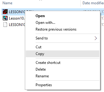
5. Rename the copied file to Lesson10a.dsn
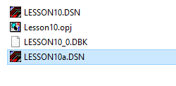
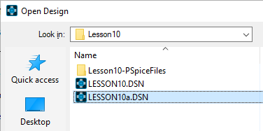
6. Restore the Capture window from the Task Bar, then File>Open>Design and browse to C:\OrCAD_Training\Capture\Lesson10, select the Lesson10a.dsn file and left-click>Open
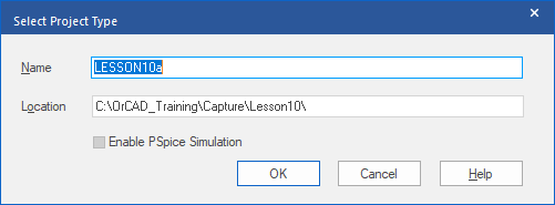
7. Left-click>OK when the Select Project Type form appears.
8. If necessary, open the “+” entries in the Project Window to get Schematic1 opened to show the Pages, double-click on either Page1, or Page2, to open the schematic page with the Header and Caps placed on it
(This could be either page depending upon exactly what steps you took in the previous labs. It doesn’t matter if you have both pages open, just start working on the one with the Header and Caps)
9. Window select all of the connections for the Q nets and bus and then right-click>Delete, or press the Del key, to remove them
10. Then window select the Load, Clock, Clear nets and delete those as well.
(You may need to make a couple of window selects to avoid removing the VCC and GND connections which need to be retained. You can use the Selection Filter and select only Markers to delete the DRC Markers so that the Pins are “exposed”. Remember to set the Selection Filter back to “All” for subsequent selections)
11. Once the signal wiring is removed, from the main menu, select Place>NetGroup
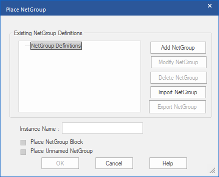
12. When the Place NetGroup dialog opens, left-click>Add NetGroup, specify “mainbus” as the NetGroup name and left-click on Apply
(This will be converted to uppercase when the NetGroup finally gets added)
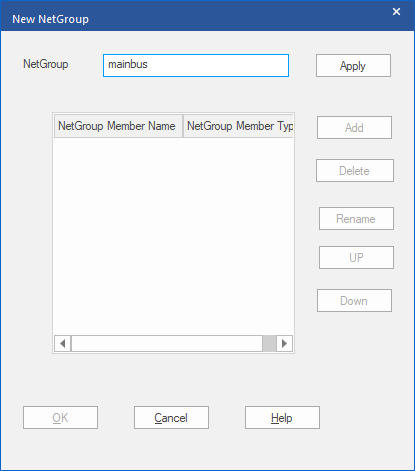
13. Left-click>Add to add NetGroup Members
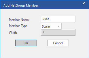
14. In the Add NetGroup Member dialog add the following Member names and types:
Clock Scalar
Load Scalar
Clear Scalar
Q[0-3] Bus
(OK to add the NetGroup member and Add again to add the next NetGroup member)
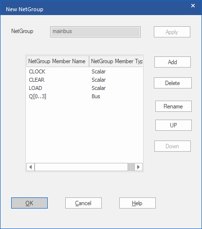
15. Left-click>OK to add the NetGroup
16. Left-click>OK the message that the DSN file will be saved after NetGroup creation
The NetGroup will then be listed in Place NetGroup
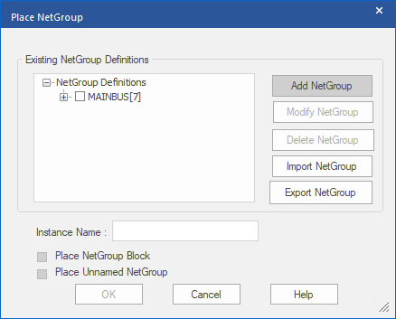
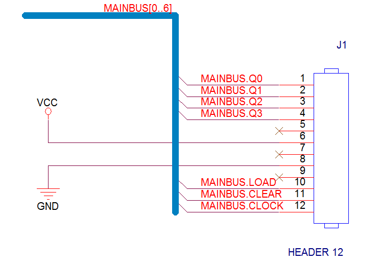
17. Check the box next to MAINBUS[7], then OK will be enabled so left-click on it to start placing the NetGroup. The Capture cursor will be a “+”, left-click to start drawing the NetGroup, left-click to add corners and right-click>End Wire once you have added the end of the NetGroup. (see below)
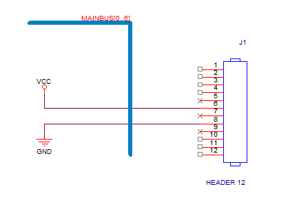
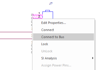
18. Window select the top 4 pins of the Header 12 part and right-click>Connect to Bus.
19. The cursor will change to an “X”, then left-click on the drawn NetGroup
20. The Select Nets dialog will be displayed, check “+” to expand MAINBUS[0..6] and check the box for MAINBUS.Q[0..3]
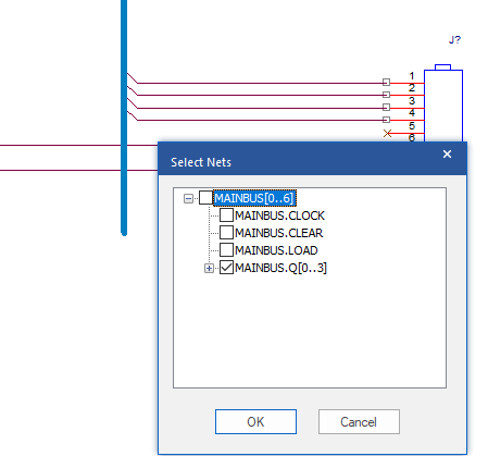
21. Left-click>OK
The 4 wires will be named with the MAINBUS Net Aliases.
22. Repeat this process to add the Load, Clear and Clock NetGroup members, then right-click>End Mode to exit the “Connect to Bus” operation.
You can move the Net Aliases around on the wires to improve appearance, if required, just left-click on the Net Alias and drag
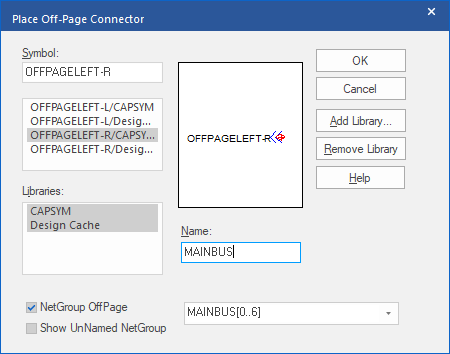
23. Next use Place>Off-Page Connector, pick OFFPAGELEFT-R from the list of available symbols, check the NetGroup OffPage option, and set the Name to MAINBUS, see the screen shot below for details
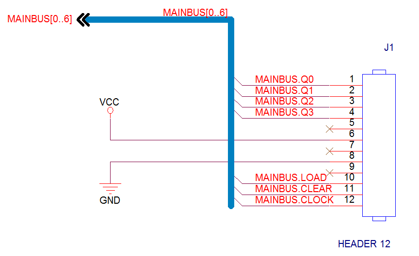
24. Left-click>OK to get the Off-Page Connector onto the cursor and left-click to place it at the upper left end of the drawn NetGroup
25. Use File>Save from the main menu to save the changes and move to the other schematic page, the one with the Counter and Gate on it.
26. Window select and delete the existing wires and bus connections, the connections to the Gate will be restored later in this lab
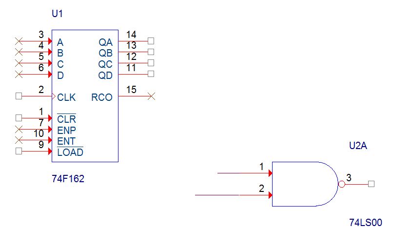
27. Use Place>NetGroup and select the MAINBUS[7] entry, OK to close the dialog and draw the NetGroup to make the connections later
Use right-click>End Wire to move onto adding another section. End Wire twice to end adding the NetGroup sections
You can “drag the NetGroup alias around” to improve appearance, if required
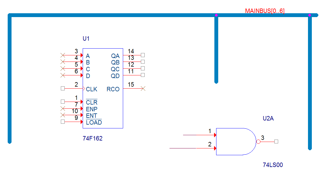
28. Window select the 4 pins of the Counter outputs on the right, hover over one of them and right-click>Connect to Bus, then left-click on the NetGroup section to make the connection, select MAINBUS.Q[0..3] and the Net Aliases for the NetGroup members will be added
(Don’t worry about moving the Net Aliases to a “nicer” position for now, that can be done once all of the Net Group member connections have been made)
29. Now work round the remaining unconnected pins and make the NetGroup connections for them, Clock, Clear and Load, and right-click>End Mode to end adding the NetGroup member connections
30. You can now drag the Net Aliases around to tidy things up, if required
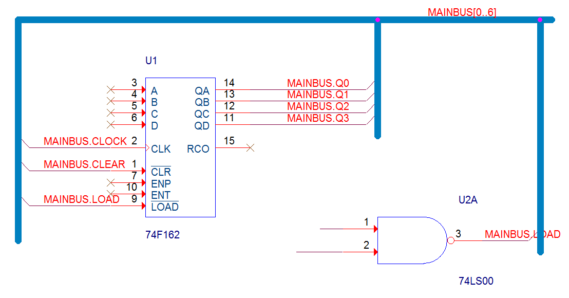
31. Complete the connections to the Gate with Place>Wire
32. And, finally, use Place>Off-Page Connector to add the NetGroup Off-Page Connector, OFFPAGELEFT-L, check the NetGroup OffPage and change the Name to MAINBUS before placing onto the end of the NetGroup
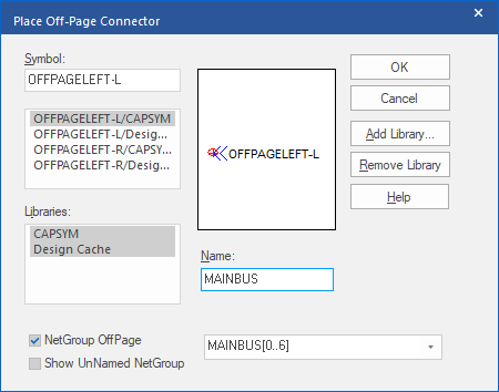
(You could use an OFFPAGELEFT-R and rotate the symbol twice before placing it onto the NetGroup. Remember that the graphical appearance of an Off-Page Connector has no meaning as far as signal direction is concerned)
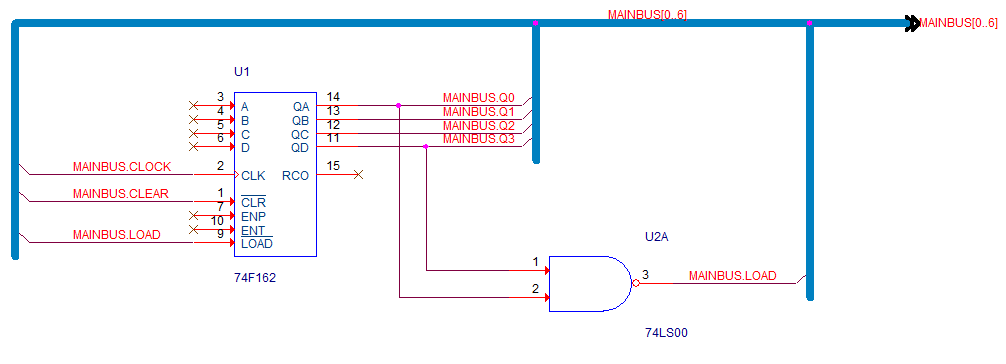
33. Switch to the Lesson10a tab, select the “dsn” file entry and use File>Save to save the completed design.
34. Select File>Close from the top menu to close Lesson10a, this design won’t be need for any subsequent labs.

End of Lab
All content Copyright 2022 Parallel Systems Ltd.