
All content Copyright 2022 Parallel Systems Ltd.
Note
An alternate method for doing some of the following labs is to use the Property Editor and the Edit Object Properties method from the Project Manager window.
Get to the Object Properties as follows:
(steps 1-3 can be skipped since the Object Properties method is not used in this lab)
1. In the Training Project Manager window, left-click the .\training.dsn, entry and select Edit>Object Properties from the top menu.
The Property Editor window opens displaying the current properties of all of the parts in the design.
2. Set Filter by to: OrCAD PCB Designer Professional.
3. Close the Property Editor.
4. Select Edit>Browse>Parts from the top menu.
5. Left-click>OK to continue.
The Browse Parts window lists all the parts in the design.
6. Scroll down through the Parts and locate the Value EPF8282A_LCC in the list.
7. Left-click on that entry and use Edit>Properties from the main menu.
The Browse Spreadsheet displays all properties currently attached to U5.
8. Locate the PCB Footprint property to verify a cell value of PLCC84.
9. If necessary, left-click in the cell, and enter:
PLCC84
10. Left-click>OK to continue.
11. Close the Browse Parts window, and save the design.
12. In the Project Manager window, left-click on the .\training.dsn entry, select Edit>Browse>Nets from the top menu and left-click>OK to continue.
13. Left-click on the ObjectID heading to sort the values by Net Name.
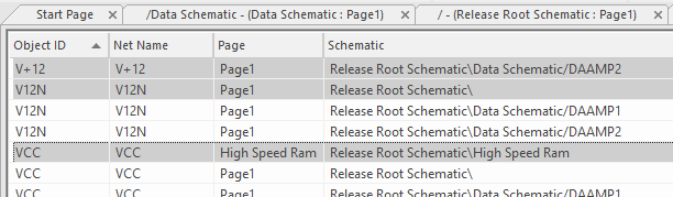
The Browse Nets window lists all the nets in the design.
The following is one method you can use to add net properties to wires.
14. Use Control+left-click to select just one Object ID for each of the following nets:
AGND, GND, GND_EARTH, V12N, VCC, and V+12
15. Select Edit>Properties from the top menu (or press Control+E).
The Browse Spreadsheet opens and displays properties currently attached to these six nets.
16. Left-click>New.
17. Enter NET_PHYSICAL_TYPE in the Name field.
18. Enter the value:
POWER
19. Left-click>OK to continue.
20. Locate the NET_PHYSICAL_TYPE property column. Verify the column values.
Note
A new value can also be set for all cells, as follows:
• Left-click in the first cell in the NET_PHYSICAL_TYPE column.
• Enter a desired value.
• Copy the value.
• Left-click on column header and paste.
The property value you copied is pasted into all column cells.
21. Left-click>New.
22. Enter NET_SPACING_TYPE in the Name field.
23. Enter the value:
POWER
24. Left-click>OK to continue.
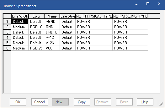
25. Left-click>OK to close the Browse Nets window, and save the design.
The following is only one of the ways to assign a property to parts in the Capture Schematic.
26. In the Project Manager window, left-click on the DAAMP Circuit schematic folder to select it and select Edit>Browse>Parts from the top menu.
27. Left-click>OK to continue.
The Browse Parts window lists every occurrence of every part found in the DAAMP1 and DAAMP2 blocks.
28. Widen the column labelled Schematic to see the entire schematic path for each occurrence.
29. Left-click on the Schematic column heading to sort the entries by Schematic.
All the DAAMP1 parts are now at the top of the list.
The result is shown in the following picture.
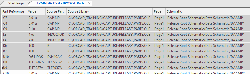
30. In the Reference column, left-click on the upper left Reference Cell, C7, and use Shift+left-click on the last entry for DAAMP1, U9, to group select all the parts on the DAAMP1 page (as shown above).
31. Select Edit>Properties from the top menu. or press Control+E.
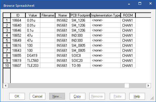
The Browse Spreadsheet appears, listing the selected part occurrences and their current properties.
32. Use the New button at the bottom of the window to add a Property called ROOM and a value of CHAN1
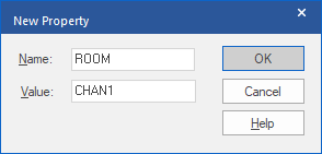
33. Left-Click>OK to set the value.
34. Scroll across to the end of the values to verify that the value has been added.
35. Left-click>OK to close the Browse Spreadsheet.
All the parts in the DAAMP1 block now have a ROOM property with a value of CHAN1.
36. Repeat the steps above, selecting the parts for the DAAMP2 block, and add a new ROOM Property with a value of CHAN2.
37. To verify the changes, double-click on PAGE1 page in the DAAMP Circuit folder.
The Select Occurrence window appears.
38. Left-click>OK to open one of the Data/DAAMP schematic instances.
39. If necessary, zoom to fit.
40. Drag a window around the schematic contents to select all of the objects in the design.
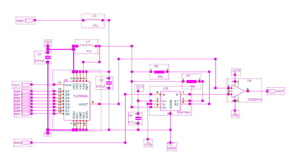
41. Right-click>Edit Properties.
42. Left-click on the Parts tab at the bottom of the Property Editor (Schematic Nets will probably be active which won’t display the required Part properties to check)
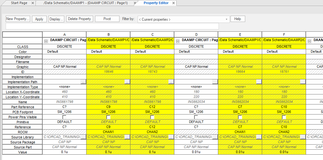
Instances properties appear in the white column, and Occurrences properties appear in the two yellow columns (one column for DAAMP1, and another column for DAAMP2).
43. Set the Filter by field to OrCAD PCB Designer Professional.
44. Locate the ROOM property and observe the different values in the DAAMP1 and DAAMP2 columns.
45. Close the Property Editor.
46. Save the design.
End of Lab
All content Copyright 2022 Parallel Systems Ltd.